40 KiB
Display drivers for nano-gui
The nano-gui project currently supports four display technologies: OLED (color
and monochrome), color TFT, monochrome Sharp displays and EPD (ePaper/eInk).
All drivers provide a display class subclassed from the built-in
framebuf.FrameBuffer class. This provides three increasing levels of support:
- Graphics via the
FrameBuffergraphics primitives. - Text rendering in arbitrary fonts via
WriterandCwriterclasses (see font_to_py.py). - Use with nano-gui.
It should be noted that in the interests of conserving RAM these drivers offer a bare minimum of functionality required to support the above.
Main README
Contents
- Introduction
1.1 Color handling - Drivers for SSD1351 Color OLEDs
- Drivers for SSD1331 Small color OLEDs
- Drivers for ST7735R Small color TFTs
- Drivers for ILI9341 Large color TFTs
- Drivers for sharp displays Large low power monochrome displays
6.1 Display characteristics
6.1.1 The VCOM bit
6.1.2 Refresh rate
6.2 Test scripts
6.3 Device driver constructor
6.3.1 Device driver methods
6.3.2 The vcom arg
6.4 Application design
6.4.1 Micropower applications
6.5 Resources - ePaper displays
7.1 Adafruit monochrome eInk Displays
7.1.1 EPD constructor args
7.1.2 EPD public methods
7.1.3 EPD public bound variables
7.1.4 FeatherWing Wiring
7.2 Waveshare eInk Display HAT
7.2.1 EPD constructor args
7.2.2 EPD public methods
7.2.3 EPD public bound variables - EPD Asynchronous support
- Writing device drivers
Main README
1. Introduction
An application specifies a driver by means of color_setup.py located in the
root directory of the target. This typically contains code along these lines:
import machine
import gc
from drivers.ssd1351.ssd1351 import SSD1351 as SSD  # Choose device driver
pdc = machine.Pin('Y1', machine.Pin.OUT_PP, value=0)
pcs = machine.Pin('Y2', machine.Pin.OUT_PP, value=1)
prst = machine.Pin('Y3', machine.Pin.OUT_PP, value=1)
spi = machine.SPI(2, baudrate=10_000_000)  # baudrate depends on display chip
gc.collect()
# Precaution before instantiating framebuf. The next line creates the buffer.
ssd = SSD(spi, pcs, pdc, prst, 96)  # Create a display instance
The directory color_setup contains example files for various displays. These
may be adapted and copied to color_setup.py on the target's root. The entry
in this doc for the specific display should be consulted for SSD constructor
arguments and SPI baudrate. The more exotic displays (Sharp and ePaper) have
additional features and requirements detailed below.
1.1 Color handling
Most color displays support colors specified as 16-bit quantities. Storing two
bytes for every pixel results in large frame buffers. Most of the drivers
reduce this to 1 byte (the default) or 4 bits per pixel, with the data being
expanded at runtime when a line is displayed. This trades a large saving in RAM
for a small increase in refresh time. Minimising this increase while keeping
the driver cross-platform involves the use of the viper decorator.
Eight bit drivers store colors in rrrgggbb. This results in a loss of
precision in specifying a color. Four bit drivers store a color as the index
into a 16 bit lookup table. There is no loss of precision but only 16 distinct
colors can be supported.
The choice of 16, 8 or 4 bit drivers is largely transparent: all demo scripts run in a visually identical manner under all drivers. This will apply to any application which uses the predefined colors. Differences become apparent when specifying custom colors. For detail see the main README User defined colors.
Contents
2. Drivers for SSD1351
This is an OLED driver. The supported displays produce excellent images with extreme contrast and bright colors. Power consumption is low.
See Adafruit 1.5" 128*128 OLED display and Adafruit 1.27" 128*96 display.
There are four versions.
ssd1351.pyThis is optimised for STM (e.g. Pyboard) platforms.ssd1351_generic.pyCross-platform version. Tested on ESP32 and ESP8266.ssd1351_16bit.pyCross-platform. Uses 16 bit RGB565 color.ssd1351_4bit.pyCross-platform. Uses 4 bit color.
All these drivers work with the provided demo scripts.
To conserve RAM the first two use 8 bit (rrrgggbb) color. This works well with
the GUI if saturated colors are used to render text and controls.
The ssd1351_generic.py and 4 bit versions use the micropython.viper
decorator. If your platform does not support this, comment it out and remove
the type annotations. You may be able to use the micropython.native
decorator.
If the platform supports the viper emitter performance should still be good: on a Pyboard V1 the generic driver perorms a refresh of a 128*128 color display in 47ms. The STM version is faster but not by a large margin: a refresh takes 41ms. 32ms of these figures is consumed by the data transfer over the SPI interface. The 4-bit version with Viper takes 44ms.
If the viper and native decorators are unsupported a screen redraw takes 272ms (on Pyboard 1.0) which is visibly slow.
The ssd1351_16bit version on a 128x128 display requires 32KiB for the frame
buffer; this means it is only usable on platforms with plenty of RAM. Testing
was done on a Pyboard D SF2W. With the GUI this version offers no benefit, but
it delivers major advantages in applications such as rendering images.
For further information see the GUI README User defined colors.
This driver was tested on Adafruit 1.5 and 1.27 inch displays.
The color_setup.py file should initialise the SPI bus with a baudrate of
20_000_000. Args polarity, phase, bits, firstbit are defaults. Hard or
soft SPI may be used but hard may be faster.
SSD1351 Constructor args:
spiAn SPI bus instance.pincsAn initialised output pin. Initial value should be 1.pindcAn initialised output pin. Initial value should be 0.pinrsAn initialised output pin. Initial value should be 1.height=128Display dimensions in pixels. Height must be 96 or 128.width=128init_spi=FalseThis optional arg enables flexible options in configuring the SPI bus. The default assumes exclusive access to the bus withcolor_setup.pyinitialising it. Those settings will be left in place. If a callback function is passed, it will be called prior to each SPI bus write: this is for shared bus applications. The callback will receive a single arg being the SPI bus instance. In normal use it will be a one-liner or lambda initialising the bus. A minimal example is this function:
def spi_init(spi):
    spi.init(baudrate=20_000_000)  # Data sheet: should support 20MHz
Despite the datasheet I failed to get this baudrate to work even on a PCB.
A "gotcha" in the datasheet
For anyone seeking to understand or modify the code, the datasheet para 8.3.2
is confusing. They use the colors red, green and blue to represent colors C, B
and A. With the setup used in these drivers, C is blue and A is red. The 16 bit
color streams sent to the display are:
s[x] 1st byte sent b7 b6 b5 b4 b3 g7 g6 g5
s[x + 1] 2nd byte sent g4 g3 g2 r7 r6 r5 r4 r3
Contents
3. Drivers for SSD1331
This is an OLED driver for small displays. The supported display produces excellent images with extreme contrast and bright colors. Power consumption is low.
See Adafruit 0.96" OLED display. Most
of the demos assume a larger screen and will fail. The color96.py demo is
written for this display.
There are two versions. Both are cross-platform.
ssd1331.pyUses 8 bit rrrgggbb color.ssd1331_16bit.pyUses 16 bit RGB565 color.
The ssd1331_16bit version requires 12KiB of RAM for the frame buffer, while
the standard version needs only 6KiB. For the GUI the standard version works
well because text and controls are normally drawn with a limited range of
colors, most of which are saturated.
The 16 bit version provides greatly improved results when rendering images.
The color_setup.py file should initialise the SPI bus with a baudrate of
6_666_000. Args polarity, phase, bits, firstbit are defaults. Hard or
soft SPI may be used but hard may be faster.
SSD1331 Constructor args:
spiAn SPI bus instance.pincsAn initialised output pin. Initial value should be 1.pindcAn initialised output pin. Initial value should be 0.pinrsAn initialised output pin. Initial value should be 1.height=64Display dimensions in pixels.width=96init_spi=FalseThis optional arg enables flexible options in configuring the SPI bus. The default assumes exclusive access to the bus withcolor_setup.pyinitialising it. Those settings will be left in place. If a callback function is passed, it will be called prior to each SPI bus write: this is for shared bus applications. The callback will receive a single arg being the SPI bus instance. In normal use it will be a one-liner or lambda initialising the bus. A minimal example is this function:
def spi_init(spi):
    spi.init(baudrate=6_666_000)  # Data sheet: max is 150ns
Contents
4. Drivers for ST7735R
This chip is for small TFT displays. Four drivers are provided. All are
cross-platform but assume micropython.viper capability. They use 8-bit or
4-bit color to minimise the RAM used by the frame buffer.
Drivers for Adafruit 1.8" display.
st7735r.py8-bit color.st7735r_4bit.py4-bit color for further RAM reduction.
st7735r144.py8-bit color.st7735r144_4bit4 bit color.
Users of other ST7735R based displays should beware: there are many variants with differing setup requirements. This driver has four different initialisation routines for various display versions. The supported Adafruit displays differ in their initialisation settings, hence the need for different drivers for the two display types. If your Chinese display doesn't work with my drivers you are on your own: I can't support hardware I don't possess.
The color_setup.py file should initialise the SPI bus with a baudrate of
12_000_000. Args polarity, phase, bits, firstbit are defaults. Hard or
soft SPI may be used but hard may be faster.
ST7735R Constructor args 1.8" display:
spiAn initialised SPI bus instance. The device can support clock rates of upto 15MHz.csAn initialised output pin. Initial value should be 1.dcAn initialised output pin. Initial value should be 0.rstAn initialised output pin. Initial value should be 1.height=128Display dimensions in pixels. For portrait mode exchangeheightandwidthvalues.width=160usd=FalseUpside down: setTrueto invert display.init_spi=FalseThis optional arg enables flexible options in configuring the SPI bus. See below.
ST7735R144 Constructor args 1.44" display:
spiAn initialised SPI bus instance. The device can support clock rates of upto 15MHz.csAn initialised output pin. Initial value should be 1.dcAn initialised output pin. Initial value should be 0.rstAn initialised output pin. Initial value should be 1.height=128Display dimensions in pixels.width=128rotation=0Pass 0, 90, 180 or 270 to rotate the display.init_spi=FalseThis optional arg enables flexible options in configuring the SPI bus. See below.
The init_spi constructor arg
The False default assumes exclusive access to the bus. It is initialised by
color_setup.py and those settings are left in place. If a callback function
is passed, it will be called prior to each SPI bus write. This is for shared
bus applications. The callback will receive a single arg being the SPI bus
instance. In normal use it will be a one-liner or lambda initialising the bus.
A minimal example is this function which caters for the case where another
program may have changed the baudrate:
def spi_init(spi):
    spi.init(baudrate=12_000_000)  # Data sheet: max is 12MHz
Contents
5. Drivers for ILI9341
Adafruit make several displays using this chip, for example this 3.2 inch unit.
The color_setup.py file should initialise the SPI bus with a baudrate of
10_000_000. Args polarity, phase, bits, firstbit are defaults. Hard or
soft SPI may be used but hard may be faster. See note on overclocking below.
ILI9341 Constructor args:
spiAn initialised SPI bus instance. The device can support clock rates of upto 10MHz.csAn initialised output pin. Initial value should be 1.dcAn initialised output pin. Initial value should be 0.rstAn initialised output pin. Initial value should be 1.height=240Display dimensions in pixels. For portrait mode exchangeheightandwidthvalues.width=320usd=FalseUpside down: setTrueto invert display.init_spi=FalseThis optional arg enables flexible options in configuring the SPI bus. The default assumes exclusive access to the bus. In this normal case,color_setup.pyinitialises it and the settings will be left in place. If the bus is shared with devices which require different settings, a callback function should be passed. It will be called prior to each SPI bus write. The callback will receive a single arg being the SPI bus instance. It will typically be a one-liner or lambda initialising the bus. A minimal example is this function:
def spi_init(spi):
    spi.init(baudrate=10_000_000)
The ILI9341 class uses 4-bit color to conserve RAM. Even with this adaptation
the buffer size is 37.5KiB. See Color handling
for details of the implications of 4-bit color. On a Pyboard 1.1 the scale.py
demo ran with 34.5K free with no modules frozen, and with 47K free with gui
and contents frozen.
The driver uses the micropython.viper decorator. If your platform does not
support this, comment it out and remove the type annotations. You may be able
to use the micropython.native decorator.
Use with uasyncio
A full refresh blocks for ~200ms. If this is acceptable, no special precautions
are required. However this period may be unacceptable for some uasyncio
applications. The driver provides an asynchronous do_refresh(split=4) method.
If this is run the display will regularly be refreshed, but will periodically
yield to the scheduler enabling other tasks to run. The arg determines the
number of times this will occur, so by default it will block for about 50ms.
A ValueError will result if split is not an integer divisor of the display
height.
An application using this should call refresh(ssd, True) once at the start,
then launch the do_refresh method. After that, no calls to refresh should
be made. See gui/demos/scale_ili.py.
Another option to reduce blocking is overclocking the SPI bus.
Overclocking SPI
The ILI9341 datasheet section 19.3.4 specifies a minimum clock cycle time of 100ns for write cycles. It seems that every man and his dog overclocks this, even the normally conservative Adafruit use 24MHz and rdagger uses 40MHz. I have successfully run my display at 40MHz. My engineering training makes me baulk at exceeding datasheet limits but the choice is yours. I raised this isse. The response may be of interest.
Contents
6. Drivers for sharp displays
These displays have characteristics which mean that they are best suited to micropower applications. Inevitably this means that deployment is more involved than the other supported units. This doc provides some background information on their use.
These monochrome SPI displays exist in three variants from Adafruit.
- 2.7 inch 400x240 pixels
- 1.3 inch 144x168
- 1.3 inch 96x96 - Discontinued.
I have tested on the first of these. However the Adfruit driver supports all of these and I would expect this one also to do so.
6.1. Display characteristics
These displays have extremely low current consumption: I measured ~90μA on the 2.7" board when in use. Refresh is fast, visually excellent and can run at up to 20Hz. This contrasts with ePaper (eInk) displays where refresh is slow (seconds) and visually intrusive; an alternative fast mode overcomes this, but at the expense of ghosting.
On the other hand the power consumption of ePaper can be zero (you can switch them off and the display is retained). If you power down a Sharp display the image is retained, but only for a few seconds. In a Pyboard context 90μA is low in comparison to stop mode and battery powered applications should be easily realised.
The 2.7" display has excellent resolution and can display fine lines and small fonts. In other respects the display quality is not as good as ePaper. For good contrast best results are achieved if the viewing angle and the direction of the light source are positioned to achieve reflection.
6.1.1 The VCOM bit
The significance of this is somewhat glossed-over in the Adafruit docs, and a study of the datasheet is confusing in the absence of prior knowledge of LCD technology.
The signals applied to an LCD display should have no DC component. This is because DC can cause gradual electrolysis and deterioration of of the liquid crystal material. Display driver hardware typically has an oscillator driving exclusive-or gates such that antiphase signals are applied for ON pixels, and in-phase for OFF pixels. The oscillator typically drives a D-type flip-flop to ensure an accurate 1:1 mark space ratio and hence zero DC component.
These displays offer two ways of achieving this, in the device driver or using
an external 1:1 mark space logic signal. The bit controlling this is known as
VCOM and the external pins supporting it are EXTMODE and EXTCOMIN.
EXTMODE determines whether a hardware input is used (Vcc) or software
control is required (Gnd). It is pulled low.
The driver supports software control, in that VCOM is complemented each time
the display is refreshed. The Adafruit driver also does this.
Sofware control implies that, in long running applications, the display should regularly be refreshed. The datasheet incicates that the maximum rate is 20Hz, but a 1Hz rate is sufficient.
If hardware control is to be used, EXTMODE should be linked to Vcc and a
1:1 logic signal applied to EXTCOMIN. A frequency range of 0.5-10Hz is
specified, and the datasheet also specifies "EXTCOMIN frequency should be
made lower than frame frequency".
In my opinion the easiest way to deal with this is usually to use software
control, ensuring that the driver's show method is called at regular
intervals of at least 1Hz.
6.1.2 Refresh rate
The datasheet specifies a minimum refresh rate of 1Hz.
6.2. Test scripts
sharptest.pyBasic functionality test.clocktest.pyDigital and analog clock display.clock_batt.pyAs above but designed for low power operation. Pyboard specific.
Tests assume that nanogui is installed as per the instructions. sharptest
should not be run for long periods as it does not regularly refresh the
display. It tests writer.py and some framebuffer graphics primitives.
clocktest demostrates use with nanogui.
The clock_batt.py demo needs upower.py from
micropython-micropower.
Testing was done on a Pyboard D SF6W: frozen bytecode was not required. I suspect a Pyboard 1.x would require it to prevent memory errors. Fonts in particular benefit from freezing as their RAM usage is radically reduced.
6.3. Device driver constructor
Positional args:
spiAn SPI bus instance. The constructor initialises this to the baudrate and bit order required by the hardware.pincsAPininstance. The caller should initialise this as an output with value 0 (unusually the hardware CS line is active high).height=240Dimensions in pixels. Defaults are for 2.7" display.width=400vcom=FalseAccept the default unless usingpyb.standby. See 6.3.2.
6.3.1 Device driver methods
showNo args. Transfers the framebuffer contents to the device, updating the display.updateToggles theVCOMbit without transferring the framebuffer. This is a power saving method for cases where the application callsshowat a rate of < 1Hz. In such casesupdateshould be called at a 1Hz rate.
6.3.2 The vcom arg
It purpose is to support micropower applications which use pyb.standby.
Wakeup from standby is similar to a reboot in that program execution starts
from scratch. In the case where the board wakes up, writes to the display, and
returns to standby, the VCOM bit would never change. In this case the
application should store a bool in peristent storage, toggling it on each
restart, and pass that to the constructor.
Persistent storage exists in the RTC registers and backup RAM. See micopython-micropower for details of how to acces these resources.
6.4. Application design
In all cases the frame buffer is located on the target hardware. In the case of the 2.7 inch display this is 400*240//8 = 12000 bytes in size. This should be instantiated as soon as possible in the application to ensure that sufficient contiguous RAM is available.
6.4.1 Micropower applications
These comments largely assume a Pyboard host. The application should import
upower from
micropython-micropower.
This turns the USB interface off if not in use to conserve power. It also
provides an lpdelay function to implement a delay using pyb.stop() to
conserve power.
In tests the clock_batt demo consumed 700μA between updates. A full refresh
every 30s consumed about 48mA for 128ms. These figures correspond to a mean
current consumption of 904μA implying about 46 days operation per AH of
battery capacity. LiPo cells of 2AH capacity are widely available offering a
theoretical runtime of 92 days between charges.
Lower currents might be achieved using standby but I have major doubts. This is because it is necessary to toggle the VCOM bit at a minimum of 1Hz. Waking from standby uses significan amounts of power as the modules are compiled. Even if frozen bytecode is used, there is still significant power usage importing modules and instantiating classes; this usage is not incurred in the loop in the demo.
6.5. Resources
Contents
7. ePaper displays
Known as ePaper or eInk, electrophoretic (EPD) displays are usually monochrome. Some support a few levels of grey or a very small range of colors. They have long refresh times (many seconds). The principal benefit that they consume zero current except while being refreshed: it is possible to switch off power completely with the device retaining the image indefinitely. Present day EPD units perform the slow refresh autonomously. It makes no demands on the CPU enabling user code to continue to run.
The drivers are compatible with uasyncio. One approach is to use synchronous
methods only and the standard demos (some of which use uasyncio) may be run.
However copying the framebuffer to the device blocks for some time - 250ms or
more - which may be problematic for applications which need to respond to
external events. A specific asynchronous mode provides support for reducing
blocking time. See EPD Asynchronous support.
7.1 Adafruit monochrome eInk Displays
The driver supports two Adafruit 2.9 inch 296*128 pixel units. A flexible display interfaced via their interface breakout.
An alternative is the Adafruit 2.9" eInk FeatherWing with wiring details listed below.
In my testing there are differences between these alternatives. The FeatherWing shows a black border around the display. The reason for this is unclear. Secondly, while the FeatherWing behaves as expected the image on the flexible display gradually degrades if the display is powered down. The white background becomes speckled over a period of a few minutes.
The interface breakout for the flexible display has an ENA pin which enables
the display to be powered down. This facilitates micropower applications: the
host shuts down the display before itself going into deep sleep.
The driver is cross platform and supports landscape or portrait mode. To keep the buffer size down (to 4736 bytes) there is no greyscale support. It should be noted that the Adafruit site cautions against refreshing the flexible displays more frequently than every 180s. This warning does not appear on the FeatherWing pages. No reason for the warning is given and it is unclear if this is an absolute limit or an average rate.
Wiring
The interface schematic is here. The drawing title is confusing but I believe this is the correct schematic.
The following assumes a Pyboard host. Pyboard pin numbers are based on hardware SPI 2 and an arbitrary choice of GPIO. All may be changed and soft SPI may be used.
| Pyb | Breakout |
|---|---|
| Vin | Vin (1) |
| Gnd | Gnd (3) |
| Y8 | MOSI (6) |
| Y6 | SCK (4) |
| Y4 | BUSY (11) |
| Y3 | RST (10) |
| Y2 | CS (7) |
| Y1 | DC (8) |
In normal use the ENA pin (12) may be left unconnected. For micropower use,
see below.
7.1.1 EPD constructor args
spiAn initialised SPI bus instance. The device can support clock rates of upto 10MHz.csAn initialised output pin. Initial value should be 1.dcAn initialised output pin. Initial value should be 0.rstAn initialised output pin. Initial value should be 1.busyAn initialised input pin.landscape=TrueBy default the long axis is horizontal.asyn=FalseSetting thisTrueinvokes an asynchronous mode. See EPD Asynchronous support.
7.1.2 EPD public methods
Synchronous methods
initNo args. Issues a hardware reset and initialises the hardware. This is called by the constructor. It needs to explicitly be called to exit from a deep sleep.sleepNo args. Puts the display into deep sleep. If called while a refresh is in progress it will block until the refresh is complete.sleepshould be called before a power down to avoid leaving the display in an abnormal state.readyNo args. After issuing arefreshthe device will become busy for a period:readystatus should be checked before issuingrefresh.wait_until_readyNo args. Pause until the device is ready.
Asynchronous methods
updatedAsynchronous. No args. Pause until the framebuffer has been copied to the display.waitAsynchronous. No args. Pause until the display refresh is complete.
7.1.3 EPD public bound variables
heightInteger. Height in pixels. Treat as read-only.widthInteger. Width in pixels. Treat as read-only.demo_mode=FalseBoolean. If setTrueafter instantiating,refresh()will block until display update is complete, and then for a further two seconds to enable viewing. This enables generic nanogui demos to be run on an EPD.
Micropower use
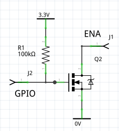
To power down the breakout the ENA pin must be pulled to 0v. Some
microcontrollers can ensure that a GPIO pin is able to sink current when the
chip goes into deep sleep. In other cases the pin becomes high impedance. The
following ensures that a high impedance pin will cause ENA to be pulled low.
The N channel MOSFET must have a low threshold voltage.
7.1.4 FeatherWing wiring
The pinout is listed here.
The busy line is brought out to a labelled pad on the PCB. It can be linked
to an unused pin on the interface connectors.
These are the connections required to run the test scripts on a Pyboard. Viwed on the underside of the board with the SD card at the top. Each connector has pairs of pins which are linked together.
| Pin | Pyb | Pin | Pyb |
|---|---|---|---|
| RST | Y3 | ||
| 3V | 3.3V | ||
| . | |||
| Gnd | Gnd | ||
| . | . | ||
| . | . | ||
| . | . | ||
| . | . | ||
| . | . | ||
| . | . | ||
| SCK | Y6 | DC | Y1 |
| MOSI | Y8 | ECS | Y2 |
| . | . | ||
| . | . | ||
| . | . | ||
| BUSY | Y4 | . |
The FeatherWing has a reset button which shorts the RST line to Gnd. To avoid risk of damage to the microcontroller pin if the button is pressed, the pin should be configured as open drain.
Contents
7.2 Waveshare eInk Display HAT
This 2.7" 176*274 display is designed for the Raspberry Pi and is detailed here.
I bought two of these units from different sources. Both have hardware issues discussed here. I have failed to achieve consistent behaviour. Units behave perfectly one day and fail the next. I published this driver on the assumption that I was twice sold dubious Chinese clones and that genuine ones would be reliable.
The driver is cross-platform.
Wiring
This shows the Raspberry Pi connector looking at the underside of the board
with the bulk of the board to the right. Only the top portion of the 40-way
connector is shown, with connections to a Pyboard to match waveshare_setup.py.
Connections may be adapted for other MicroPython targets. The board may be powered from 5V or 3.3V: there is a regulator on board.
| Pyb | L | R | Pyb | ||
|---|---|---|---|---|---|
| Vin | VIN | 2 | 1 | ||
| 4 | 3 | ||||
| 6 | 5 | ||||
| 8 | 7 | ||||
| 10 | 9 | GND | Gnd | ||
| 12 | 11 | RST | Y3 | ||
| 14 | 13 | ||||
| 16 | 15 | ||||
| Y4 | BUSY | 18 | 17 | ||
| 20 | 19 | MOSI | Y8 | ||
| Y1 | DC | 22 | 21 | ||
| Y2 | CS | 24 | 23 | SCLK | Y6 |
Pins 26-40 unused and omitted.
7.2.1 EPD constructor args
spiAn initialised SPI bus instance. The device can support clock rates of upto 2MHz.csAn initialised output pin. Initial value should be 1.dcAn initialised output pin. Initial value should be 0.rstAn initialised output pin. Initial value should be 1.busyAn initialised input pin.landscape=FalseBy default the long axis is vertical.asyn=False
7.2.2 EPD public methods
Synchronous methods
initNo args. Issues a hardware reset and initialises the hardware. This is called by the constructor. It needs to explicitly be called to exit from a deep sleep.sleepNo args. Puts the display into deep sleep. If called while a refresh is in progress it will block until the refresh is complete.sleepshould be called before a power down to avoid leaving the display in an abnormal state.readyNo args. After issuing arefreshthe device will become busy for a period:readystatus should be checked before issuingrefresh.wait_until_readyNo args. Pause until the device is ready.
Asynchronous methods
updatedAsynchronous. No args. Pause until the framebuffer has been copied to the display.waitAsynchronous. No args. Pause until the display refresh is complete.
7.2.3 EPD public bound variables
heightInteger. Height in pixels. Treat as read-only.widthInteger. Width in pixels. Treat as read-only.demo_mode=FalseBoolean. If setTrueafter instantiating,refresh()will block until display update is complete, and then for a further two seconds to enable viewing. This enables generic nanogui demos to be run on an EPD.
Contents
8. EPD Asynchronous support
Normally when GUI code issues
refresh(ssd) # 250ms or longer depending on platform
display data is copied to the device and a physical refresh is initiated. The
code blocks while copying data to the display before returning. Subsequent
physical refresh is performed by the display hardware taking several seconds.
While physical refresh is nonblocking, the initial blocking period is too long
for many uasyncio applications.
If an EPD is instantiated with asyn=True the process of copying the data to
the device is performed by a task which periodically yields to the scheduler.
By default blocking is limited to around 30ms.
A .updated() method lets user code pause after issuing refresh(). The pause
lasts until the framebuf has been entirely copied to the hardware. The
application is then free to alter the framebuf contents.
It is invalid to issue .refresh() until the physical display refresh is
complete; if this is attempted a RuntimeError will occur. The most efficient
way to ensure that this cannot occur is to await the .wait() method prior to
a refresh. This method will pause until any physical update is complete.
The following illustrates the kind of approach which may be used:
    while True:
        # Before refresh, ensure that a previous refresh is complete
        await ssd.wait()
        refresh(ssd)  # Immediate return. Creates a task to copy content to EPD.
        # Wait until the framebuf content has been passed to EPD.
        await ssd.updated()
        # Trigger an event which allows other tasks to update the
        # framebuffer in background
        evt.set()
        evt.clear()
        # The 2.9 inch display should not be updated too frequently
        await asyncio.sleep(180)
Contents
9. Writing device drivers
Device drivers capable of supporting nanogui can be extremely simple: see
drivers/sharp/sharp.py for a minimal example. It should be noted that the
supplied device drivers are designed purely to support nanogui. To conserve RAM
they provide no functionality beyond the transfer of an external frame buffer
to the device. This transfer typically takes a few tens of milliseconds. While
visually instant, this period constitutes latency between an event occurring
and a consequent display update. This may be unacceptable in applications such
as games. In such cases the FrameBuffer approach is inappropriate. Many
driver chips support graphics primitives in hardware; drivers using these
capabilities will be faster than those provided here and may often be found
using a forum search.
For a driver to support nanogui it must be subclassed from
framebuf.FrameBuffer and provide height and width bound variables being
the display size in pixels. This, and a show method, are all that is required
for monochrome drivers. Generality can be extended by providing this static
method:
    @staticmethod
    def rgb(r, g, b):
        return int(((r | g | b) & 0x80) > 0)
This ensures compatibility with code written for color displays by converting RGB values to a single bit.
Refresh must be handled by a show method taking no arguments; when called,
the contents of the buffer underlying the FrameBuffer must be copied to the
hardware.
For color drivers, to conserve RAM it is suggested that 8-bit color is used
for the FrameBuffer. If the hardware does not support this, conversion to the
supported color space needs to be done "on the fly" as per the SSD1351 driver.
This uses framebuf.GS8 to stand in for 8 bit color in rrrgggbb format. To
maximise update speed consider using native, viper or assembler for the
conversion, typically to RGB565 format.
An alternative is to design for 4-bit color which halves the size of the
framebuffer. This means using GS4_HMSB mode. The class must include the class
variable lut:
class MY_DRIVER(framebuf.FrameBuffer):
    lut = bytearray(32)
This is a lookup table (LUT) mapping a 4-bit index onto a 16-bit color value
acceptable to the hardware. The "on the fly" converter unpacks the values in
the frame buffer and uses them as indices into the lut bytearray. See the
various supplied 4-bit drivers.
Color drivers should have a static method converting rgb(255, 255, 255) to a form acceptable to the driver. For 8-bit rrrgggbb this can be:
    @staticmethod
    def rgb(r, g, b):
        return (r & 0xe0) | ((g >> 3) & 0x1c) | (b >> 6)
This should be amended if the hardware uses a different 8-bit format. If the
hardware expects a 16 bit value, the "on the fly" converter will map the 8-bit
value to 16 bits. In the case of 4-bit drivers the LUT is 16 bits in size, and
.rgb is called only when populating the LUT. In this case .rgb returns a 16
bit value in a format compatible with the hardware and the byte order of the
"on the fly" conversion code.
The convention I use is that the LS byte from .rgb() is transmitted first. So
long as .rgb() and the "on the fly" converter match, this is arbitrary.
The Writer (monochrome) or CWriter (color) classes and the nanogui module
should then work automatically.
The following script is useful for testing color display drivers after
configuring color_setup.py. It draws squares at the extreme corners of the
display and a corner to corner diagonal.
from color_setup import ssd  # Create a display instance
from gui.core.nanogui import refresh
refresh(ssd, True)  # Initialise and clear display.
ssd.fill(0)
ssd.line(0, 0, ssd.width - 1, ssd.height - 1, ssd.rgb(0, 255, 0))  # Green diagonal
ssd.rect(0, 0, 15, 15, ssd.rgb(255, 0, 0))  # Red square at top left
ssd.rect(ssd.width -15, ssd.height -15, 15, 15, ssd.rgb(0, 0, 255))  # Blue square at bottm right
ssd.show()