This is a step-by-step tutorial on generating a toolpath with Blender CAM. For detailed description of panel options go here.
 :
:
Change units to metric or imperial in Scene properties.
Add new operation in the render properties.
Setup machine parameters (postprocessor, maximum feed rate, work area, etc.) in 'CAM Machine' options.
Choose Parallel (or Outline Fill, Circles, Spiral, Block, Cross) in the Strategy dialog. Waterline option works best when OpenCAMLib is installed and other operations require curve data source. See how to generate curves from mesh model here.
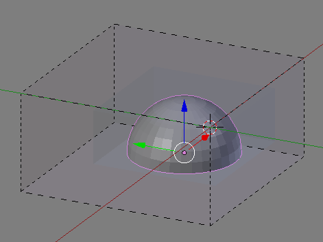
In Object dialog select object being source of geometry for toolpath generation.
In CAM Material size and position, set radius around model option to reflect the amount of stock material to be machined.
Manually position object inside work area, or use "Position object" option to position it automatically.
If the box representing material doesn't update, uncheck "Estimate from model" option and then check it again.
Set "Distance between toolpaths" to desired value.
"Distance along toolpaths" option determines accuracy. Lower values result in more accurate toolpath, but make computation slower and increase amount of resulting G-code.
Select "Use exact mode" - it improves accuracy. If you have OpenCAMLib installed, also select "UseOpenCAMLib" - it impoves accuracy and speeds up the computing time. OpenCAMLib also enables high quality algorithm from calculating waterline toolpaths.
CAM Movement:
Enter layer depth (in Step Down dialog), operation depth, start depth and optionally end depth (if "Depth from object" is disabled).
CAM Feedrate:
Set feedrate and spindle rpm. "Plunge speed" and "Plunge angle" allows slowing down feedrate when the cutter is moving down on steep areas.
Cam Cutter:
Set cutter tool number (used in G-code), type, number of flutes and diameter.
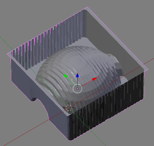
Click "Calculate Path" to generate toolpath. If "Auto export" option is selected, G-code file will also be created.

Next click "Simulate operation" to create model representing machined material.
To join multiple operations into a single G-code file, use CAM chains dialog.
Machining-technical-parts-using-Profile-and-Pocket-operations