|
|
||
|---|---|---|
| .vscode | ||
| console-decoders | ||
| img | ||
| main | ||
| .gitignore | ||
| LICENSE | ||
| README.md | ||
| platformio.ini | ||
| tbeam-workspace.code-workspace | ||
README.md
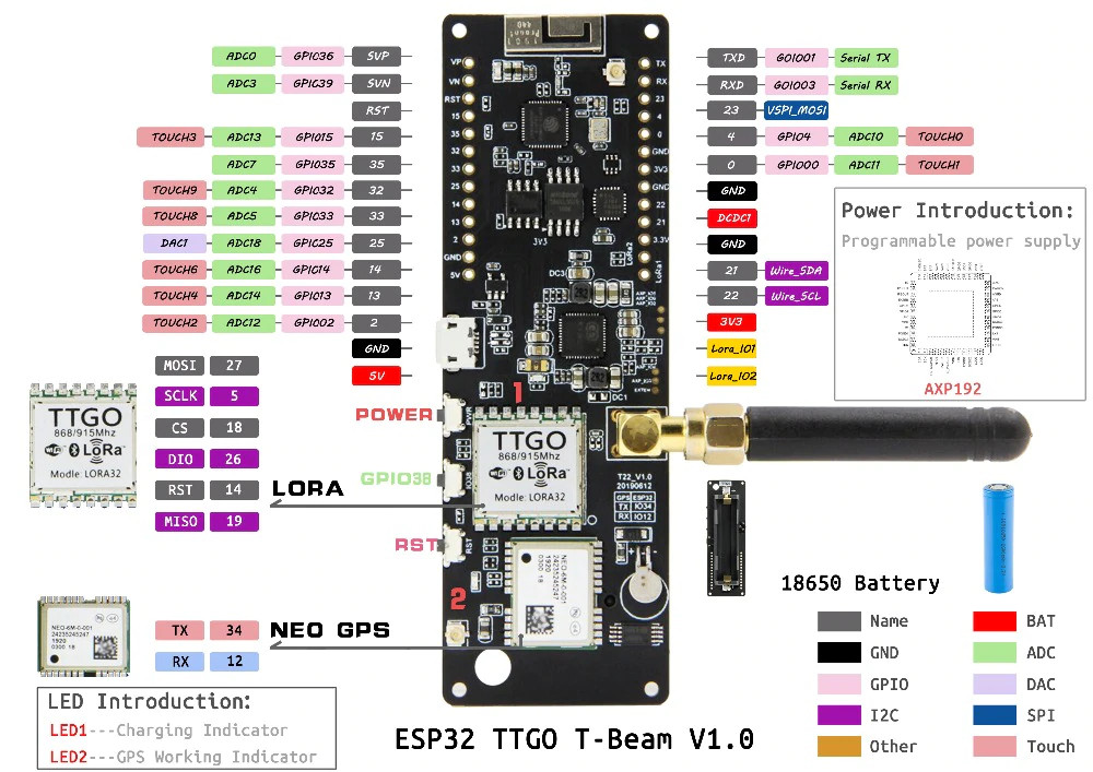
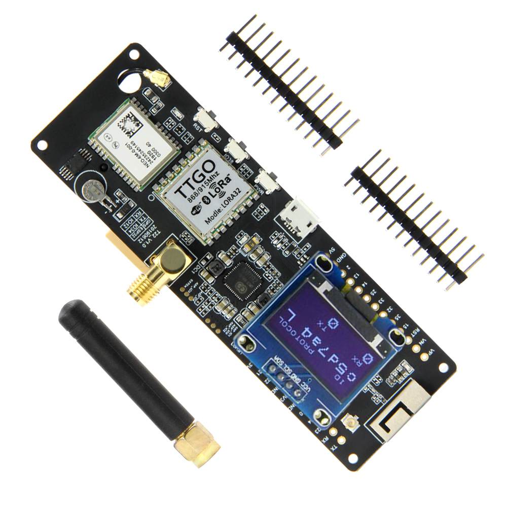
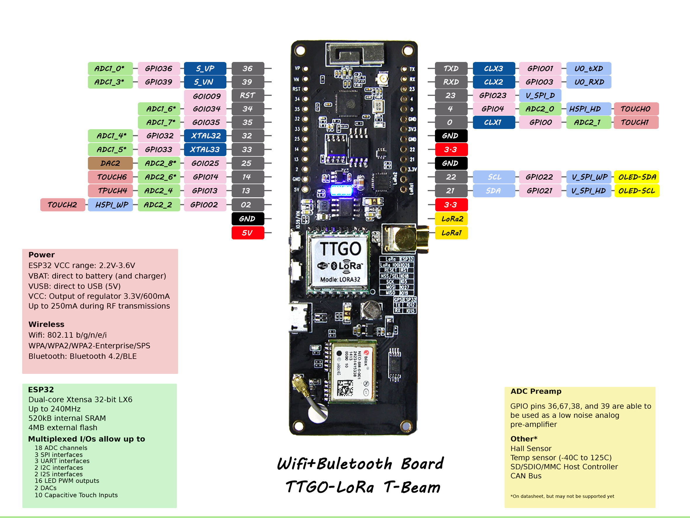
TTGO T-Beam Tracker for the Helium LoRaWAN Network and Mapper integrations.
by Max-Plastix
This build is a modification of work by many experts, with input from the Helium Discord #mappers community. Thanks to @Kicko, Fizzy, and @tmiklas especially, along with the work done on similar builds for the Heltec CubeCell mappers.
The goal of this version is to have a TTGO T-Beam that's ideally suited to vehicle mapping and tracking, taking cues from the USB Power source and movement for activity level. The Mapper is intended to be highly active while the vehicle is in motion, and quieter when the vehicle is stationary. If you want to conserve Data Credits or power, tune the default configuration to send packets less frequently.
Mandatory Configuration
Before Buliding and Uploading, you will probably want to inspect or change some items in these three files:
configuration.hplatformio.inicredentials.h
The comments and text below will guide you on what values to look out for. By default, this build is for the US915 region. Tune accordingly.
You should choose your own AppKey value in credentials.h; either take the random one suggested by the Console Device entry, or make up one of your own.
The COM Port called out in platformio.ini for Uploading and Monitoring works great on my machine, but you will have to match it to your own computer or comment them out entirely and let PlatformIO take a guess.
Theory of Operation
When your car is started, and USB Power appears, the Mapper will power on, acquire GPS, and continue mapping. It re-uses the last network Join state for faster connection and fewer packets. Ideally, there is no Join Request/Accept packet exchange at power-on.
If the Helium network resets state, or your device is out of sync, hold down the middle button to erase the last-joined state, and the device will start a fresh Join.
When running, the Mapper will send out a packet every time GPS indicates it has moved MIN_DIST meters. This is the primary knob to turn for more/fewer packets. A Helium hex cell is about 340meters across, so the default 68-meter packet distance will send quite a few redundant packets for each mapped cell. DC is incredibly cheap, but adjust to taste.
This is the normal operation of the Mapper in motion.. every MIN_DIST meters, one ping reporting position, while the battery charges from USB to a steady 4.1+ volts. If the speed of motion is fast, it may even result in back-to-back packet sends, limited by the bandwidth of your chosen Spreading Factor (Data Rate).
When the Mapper comes to a stop, staying within MIN_DIST meters, it sends a hearbeat pin every STATIONARY_TX_INTERVAL seconds (default 60). This serves to keep it visible on the map and report battery voltage. Too often? Dial up the STATIONARY_TX_INTERVAL to a longer interval.
After being stationary a long time (parked) with a decreasing battery voltage, we change to a slower pace of updates. This happens after REST_WAIT seconds (default: 30 minutes). In the Rest state, the Mapper transmits every REST_TX_INTERVAL seconds (default: 5 minutes).
Eventually, the ~100mA power drain of the mapper runs the battery down below BATTERY_LOW_VOLTAGE volts, and the Mapper will save state and completely power off.
It will power on and resume only when USB power appears.
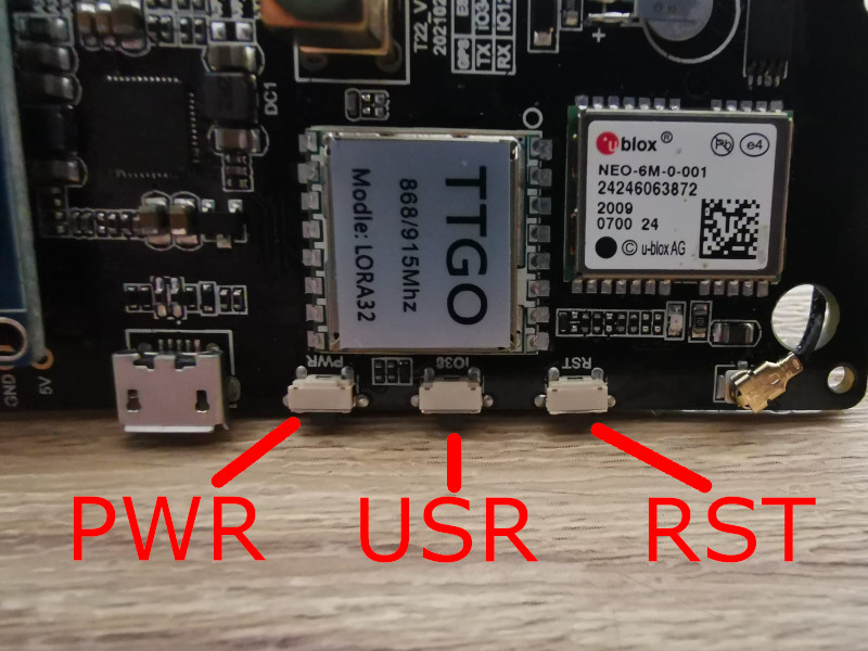
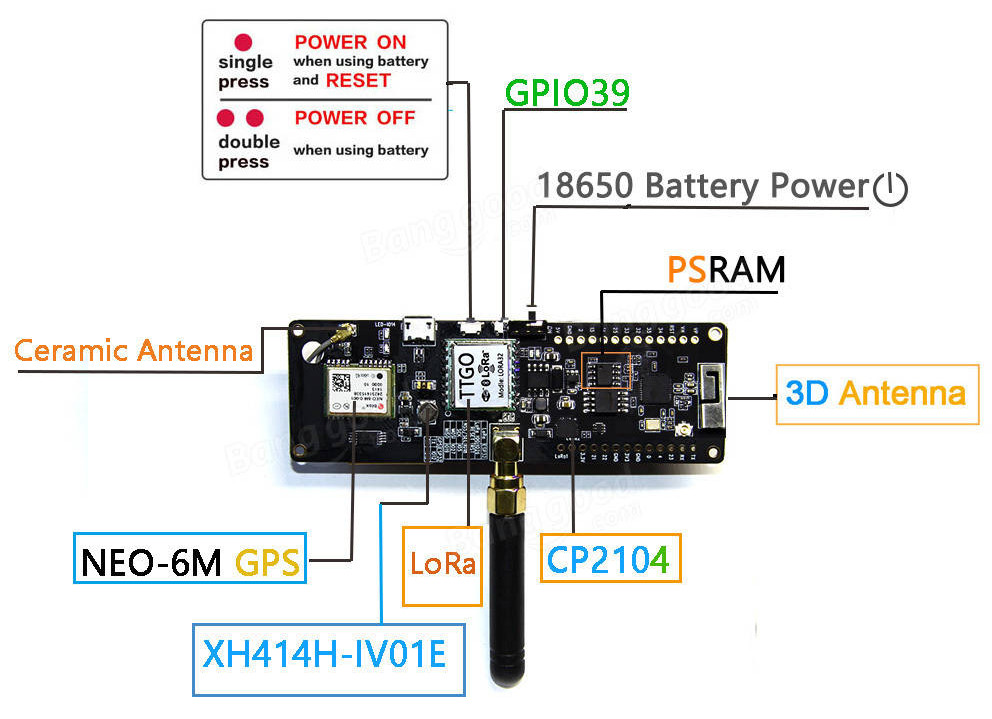
Buttons
The TTGO T-Beam has three buttons on the underside. Nearest the USB connector is the Power button. A long press on this button will turn the unit completely off. The middle button can be pressed quickly to cause an immediate packet send. A long press will erase the network state (discard Join) and re-Join. The button furthest from USB is the Reset button. It instantly reboots the device, and is not handled by software at all.
Compiling the Software
The fantastic state of PlatformIO tools makes it easiest to build and load your TTGO from source code; no pre-built binary is necessary.
By default, the DevEUI is generated automatically to be unique to each unit, but you may want to hardcode it in credentials.h instead.
I tested this software only on a LilyGo TTGO T-Beam v1.1 on US915. If you have an older v0.7 board or different region, adjust the configuration to match.
Operation
The device outputs debugging information on the USB Serial connection at 115200bps, including the network Credentials or any failures. On startup, the USB Serial port will print the DevEUI, AppID, and AppKey values, suitable for cut & paste entry into the Helium Console for your Device.
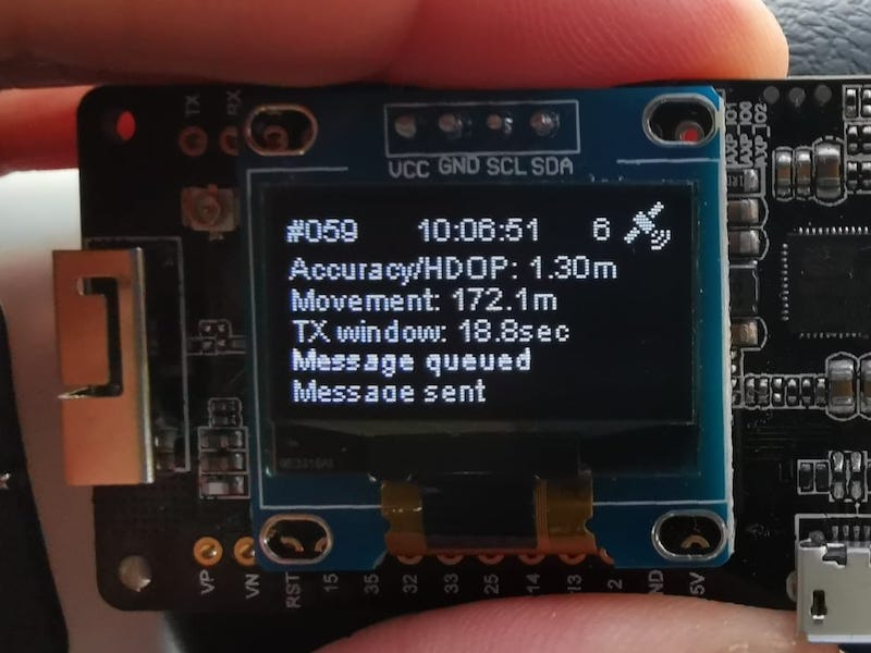
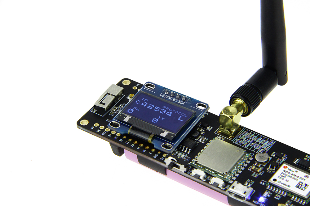
The OLED screen is always on when operating (as it uses only 10mA), and displays alternating status in the top row:
#ABCis the last three hex digits of your DevEUI, so you can match it to the correct device in Console.4.10vis the battery voltage48mAis the charge or discharge current to the battery. The TTGO charges the battery cell at around 750mA from USB, when possible.- Satellite Count is displayed on the right at all times.
- Packet Count and Time of Day (UTC) alternate on the display line every 2 seconds.
The second line shows the current operating parameters.. Time Interval, Distance Interval, and Spreading Factor / Data Rate.
The lower part of the OLED screen shows a scrolling display of four messages. Most often, it shows the Time and Distance between packet sends, and the trigger that caused the send: T for Time, D for Distance, or > for button press.
Payload
The Payload Port and byte content have been selected to match that in common use by CubeCell mappers: Lat, Long, Altitude, Speed, Battery, and Sats. This common decoder function can now be used for both TTGO and CubeCell mappers:
// From https://github.com/hkicko/CubeCell-GPS-Helium-Mapper
function Decoder(bytes, port) {
  var decoded = {};

  var latitude = ((bytes[0]<<16)>>>0) + ((bytes[1]<<8)>>>0) + bytes[2];
  latitude = (latitude / 16777215.0 * 180) - 90;

  var longitude = ((bytes[3]<<16)>>>0) + ((bytes[4]<<8)>>>0) + bytes[5];
  longitude = (longitude / 16777215.0 * 360) - 180;

  switch (port)
  {
    case 2:
      decoded.latitude = latitude;
      decoded.longitude = longitude;

      var altValue = ((bytes[6]<<8)>>>0) + bytes[7];
      var sign = bytes[6] & (1 << 7);
      if(sign) decoded.altitude = 0xFFFF0000 | altValue;
      else decoded.altitude = altValue;

      decoded.speed = parseFloat((((bytes[8]))/1.609).toFixed(2));
      decoded.battery = parseFloat((bytes[9]/100 + 2).toFixed(2));
      decoded.sats = bytes[10];
      decoded.accuracy = 2.5; // Bogus Accuracy required by Cargo/Mapper integration
      break;
  }

  return decoded;
}
Downlink
This builds adds the option to reconfigure the Mapper remotely via Helium Downlink (network to device). You can change the maximum Time Interval, Distance, and Battery Cut-off voltage remotely.
Format your Downlink Payload.
You can use the downlink_encoder.py Python script to convert your intent into a Base64 Payload.
% python downlink_encoder.py --help
usage: downlink_encoder.py [-h] [--distance DISTANCE] [--time TIME] [--cutoffvolts CUTOFFVOLTS]

Encode a downlink payload for a Helium mapper.

options:
  -h, --help            show this help message and exit
  --distance DISTANCE, -d DISTANCE
                        Map distance interval (meters)
  --time TIME, -t TIME  Minimum time interval (seconds)
  --cutoffvolts CUTOFFVOLTS, -c CUTOFFVOLTS
                        Low Voltage Power Off (volts)
For example, you might want to change the Mapper to 75 meter distance, and 600 second maximum time:
% python downlink_encoder.py -d 75 -t 600
00 4B 02 58 00
AEsCWAA=
That last output AEsCWAA= is the Base64-encoded payload, read to use.
Queue the Downlink packet for transmission
Paste that payload into the Helium Console under the Downlink panel for that device. Select a specific device, then the "Cloud Down-arrow" icon on the right ("Send a manual downlink to this device") to open the Downlink panel.
Leave FPort set to the default (1), and type as default (Base64). Queue it for transmission using the Cloud down-arrow button, and the packet should appear in the Download Queue.
When the mapper next reports (uplink), it will receive this directive and show the updates on-screen. To rush things along, you can cause an immediate Uplink (& Downlink) by pressing the middle button on the TTGO.
Allowed values
Setting any value to zero will leave the present value unchanged by the downlink.
Maximum Distance interval can be 1 to 65,534 meters. Time interval can be 1 to 65,534 seconds. A special time interval of -1 indicates that you want to remove any override and revert to the time interval in the software build configuration.
Battery voltage cutoff can range from 2.0 to 4.5 volts. If you set a cutoff higher than the present battery voltage, the Mapper will immediately power down. When it reboots (on USB power present), the default battery cutoff will be restored from the software build.
None of the Downlink values persist across power-off & on; the device always reverts to compiled-in values on startup.
The remainder of this README is parts copied from earlier authors that developed this codebase. This may be out of date or no correct for this build:
Once moving, you will be able to see it operating properly and reporting TX window:
In simple terms, with distance target set to 200m (as default in this code), window scaling starts working once you travel at speed over 10m/s (36k/h or 22.3mph). There's also a lower limit - do not transmit more often than every 2sec... so with 200m target you are good up to 100m/s (360k/h or 223mph) - good luck :-P
Ref: https://github.com/helium/longfi-arduino/tree/master/TTGO-TBeam-Tracker
This code was originally developed for use on The Things Network (TTN) it has been editied/repurposed for use with the Helium Network.
This TTGO device application uploads GPS data from the TTGO T-Beam to be used for tracking and determining signal strength of LoRaWAN gateways and nodes. When using the device and application on the Helium Network one can contribute to the Helium Network Mapper or Cargo projects. Details for the Mapper project can be found here and details for Cargo can be found here
Current version: 1.2.1
This version is based on a forked repo from github user [kizniche] https://github.com/kizniche/ttgo-tbeam-ttn-tracker. Which in turn is based on the code from xoseperez/ttgo-beam-tracker, with excerpts from dermatthias/Lora-TTNMapper-T-Beam to fix an issue with incorrect GPS data being transmitted to the network. Support was also added for the 915 MHz frequency (North and South America). lewisxhe/TTGO-T-Beam was referenced for enabling use on the newer T-Beam board (Rev1).
This is a LoRaWAN node based on the TTGO T-Beam development platform using the SSD1306 I2C OLED display. It uses a RFM95 by HopeRF and the MCCI LoRaWAN LMIC stack. This sample code is configured to connect to The LoRaWan network using the US 915 MHz frequency by default, but can be changed to EU 868 MHz.
NOTE: There are now 2 versions of the TTGO T-BEAM, the first version (Rev0) and a newer version (Rev1). The GPS module on Rev1 is connected to different pins than Rev0. This code has been successfully tested on REV0, and is in the process of being tested on REV1. See the end of this README for photos of each board.
Setup
-
Install VisualStudio Code (https://code.visualstudio.com/)
-
Add the PlattformIO extension within VS Code (https://platformio.org/install/ide?install=vscode)
-
Check Device Manager if a serialdevice appear on conntecting the T-Beam. If nothing appears a driver for the USB to serial Adpater need to be installed.(https://www.silabs.com/developers/usb-to-uart-bridge-vcp-drivers)
-
Check and edit platformio.ini to use the right bandplan for your region.
-
Edit this project file from Arduino IDE
main/configuration.hunder the Configuration section and select your correct board revision, either T_BEAM_V07 or T_BEAM_V10 (see T-BEAM Board Versions to determine which board revision you have). -
Within your project edit
main/credentials.hto add the device OTAA keys,Device EUI, App EUI and App Key. These can be found within the device configuration within the Helium console. Be sure to pay special attention to the required format when adding these credentials.
- Change to the following
-
// Only one of these settings must be defined -
//#define USE_ABP -
#define USE_OTAA - Then under * #idef USE_OTAA
-
Copy over the APP EUI (LSB), DEV EUI (LSB), APP KEY (MSB) that you copy from the Helium console
- Within the Helium Console, add a Mapper or Cargo integration.
- step by step details for setting up a Mapper integration can be found here.
- detail for setting up a Cargo integration can be found here.
The specific details for adding a Mapper or Cargo integration use a different edge node device than the one detailed here. When prompted to add a function decoder, be sure to use the following decoder. Note: This decoder can also be found within this project in the console-decoders directory.
-
Open this project file
main/main.inowith the Arduino IDE Verify/Compile the project. If the compile is successful upload the application to your TTGO T-Beam. -
Disconnect and turn on the device and once a GPS lock is acquired, the device should start sending data to the Helium network and Helium Mapper or Helium Cargo depending upon which you configured in step 6.
Using the Mapping Data
Now that your device is hopefully connecting to the Helium network refer to the following for more details about interpreting the mapping data.
- For the Helium Mapping effort visit here
- For the Helium Cargo effort visit here. Pay particular attention to the "Info" note found on this page.
T-BEAM Board Versions
Rev0
Rev1