Arguably the most important aspect of an image acquisition system is how images are represented. The SANE approach is to define a simple yet powerful representation that is sufficient for vast majority of applications and devices. While the representation is simple, the interface has been defined carefully to allow extending it in the future without breaking backwards compatibility. Thus, it will be possible to accommodate future applications or devices that were not anticipated at the time this standard was created.
A SANE image is a rectangular area. The rectangular area is subdivided into a number of rows and columns. At the intersection of each row and column is a (preferable quadratic) pixel. A pixel consists of one or more sample values. Each sample value represents one channel (e.g., the red channel).
The SANE API transmits an image as a sequence of frames. Each frame covers the same rectangular area as the entire image, but may contain only a subset of the channels in the final image. For example, a red/green/blue image could either be transmitted as a single frame that contains the sample values for all three channels or it could be transmitted as a sequence of three frames: the first frame containing the red channel, the second the green channel, and the third the blue channel.
When transmitting an image frame by frame, the frontend needs to know what part of the image a frame represents (and how many frames it should expect). For that purpose, the SANE API tags every frame with a type and a format descriptor.
There are two different types of frames: pixel oriented frames
SANE_FRAME_RAW and arbitrary data frames
SANE_FRAME_MIME. These types are discussed in detail in the
following sections. The frame types used by the previous version 1 of this
standard (SANE_FRAME_GRAY, SANE_FRAME_RGB,
SANE_FRAME_RED, SANE_FRAME_GREEN, and
SANE_FRAME_BLUE) are obsolete and superseded by
SANE_FRAME_RAW.
The type of pixel oriented frames is SANE_FRAME_RAW. The
frame contains one or more channels of data in a channel-interleaved format,
that represents sample values from a property of the individual pixels that
is subject to further description in the format_desc member of the
SANE_Parameters structured type. See section 4.3.8
on page 4.3.8 for details about the format
descriptions.
3.2.1 Pixel oriented frames
Each sample value has a certain bit depth. The bit depth is fixed for the entire image and can be as small as one bit. Valid bit depths are 1, 8, or 16 bits per sample. If a device's natural bit depth is something else, it is up to the driver to scale the sample values appropriately (e.g., a 4 bit sample could be scaled by a factor of four to represent a sample value of depth 8).
The complete image may consist of several different channels. The number of channels is defined by member channels_per_image of SANE_Parameters. The image may be transmitted in an arbitrary number of frames which can be determined by watching the SANE_PFLAG_LAST_FRAME flag in said type (or by counting the channels). Note: This frame type replaces all frame types of the SANE standard version 1.
Conceptually, each pixel oriented frame is transmitted a byte at a time. Each byte may contain 8 sample values (for an image bit depth of 1), one full sample value (for an image bit depth of 8), or a partial sample value (for an image bit depth of 16 or bigger). In the latter case, the bytes of each sample value are transmitted in the machine's native byte order.
Backend Implementation Note A network-based meta backend will have to ensure that the byte order in image data is adjusted appropriately if necessary. For example, when the meta backend attaches to the server proxy, the proxy may inform the backend of the server's byte order. The backend can then apply the adjustment if necessary. In essence, this implements a ``receiver-makes-right'' approach.

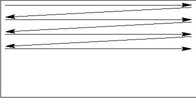
The order in which the sample values in a frame are transmitted is illustrated in Figure 2. As can be seen, the values are transmitted row by row and each row is transmitted from left-most to right-most column. The left-to-right, top-to-bottom transmission order applies when the image is viewed in its normal orientation (as it would be displayed on a screen, for example).
If a frame contains multiple channels, then the channels are transmitted in an interleaved fashion. Figure 3 illustrates this for the case where a frame contains a complete red/green/blue image with a bit-depth of 8.

For a bit depth of 1, each byte contains 8 sample values of a single channel. In other words, a bit depth 1 frame is transmitted in a byte interleaved fashion. The first sample of each byte is represented by the most significant bit.
For gray channels at a bit depth of 1 only two sample values are possible: 1
represents minimum intensity (black) and 0 represents maximum intensity
(white). For all other channel types and bit depths a sample value of 0
represents minimum intensity and larger values represent increasing intensity.
It also is possible to transmit arbitrary (not necessaryly pixel oriented)
data. This allows transmission of compressed images like jpeg, tiff, etc.
The type of arbitrary data frames is SANE_FRAME_MIME.
The frame contains arbitrary data of the MIME (see RFC 1521/1522) type that is
given in the format_desc member of the SANE_Parameters
structured type (see section 4.3.8 on
page 4.3.8). As such, it is assumed to be
incomprehensible to the frontend, except for selected types the frontend is
specifically capable of handling internally. The frontend is free to ignore
those frames, or employ any appropriate means to otherwise handle this data
(like saving them to disk or spawning an external viewer).
3.2.2 Arbitrary data frames