kopia lustrzana https://github.com/RPiks/pico-hf-oscillator
86 wiersze
4.0 KiB
Markdown
86 wiersze
4.0 KiB
Markdown
# Digital controlled radio frequency oscillator for Raspberry Pi Pico
|
|
|
|
The library for Raspberry Pi Pico includes the headers and source code and all
|
|
necessary build files to build a custom application which turns pico into
|
|
precise PLL digital frequency oscillator of the portion of HF radio spectrum
|
|
1.1 to 9.4MHz with high resolution.
|
|
|
|
# Precise frequency resolution
|
|
The library provides about 23 milli-Hz frequency resolution. This resolution is limited by 24-bit register which is used in algorithm.
|
|
The working WSPR beacon which has been built on the base of this project proves that the quality of generated signal is sufficient to such precise (~1.46 Hz step) frequency manipulation digital modes.
|
|
Currently the upper freq. limit is about 9.4 MHz and it is achieved only using Pico overclocking to 270MHz.
|
|
|
|
|
|
|
|
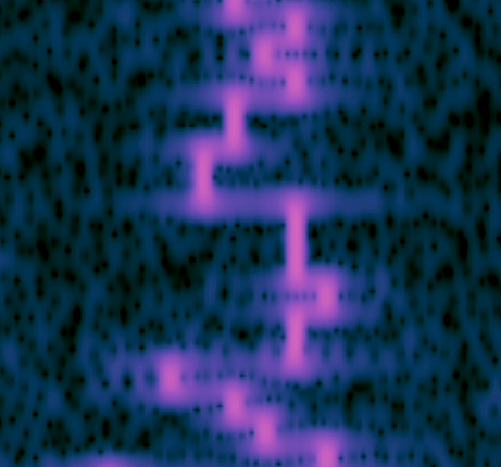
Here is an example of narrowband FSK (9.4 MHz carrier, 5 Hz step, 20 Hz range in total).
|
|
|
|
# Phased locked loop in C
|
|
The DCO uses phase locked loop principle programmed in C.
|
|
|
|
# *NO* additional hardware
|
|
The DCO provides the output signal on the GPIO pin. However if you want to
|
|
transmit the signal, you should calculate and provide a lowpass filter of
|
|
appropriate frequency. Please also figure out whether you possess rights
|
|
to emit radio frequency energy on desired frequency.
|
|
|
|
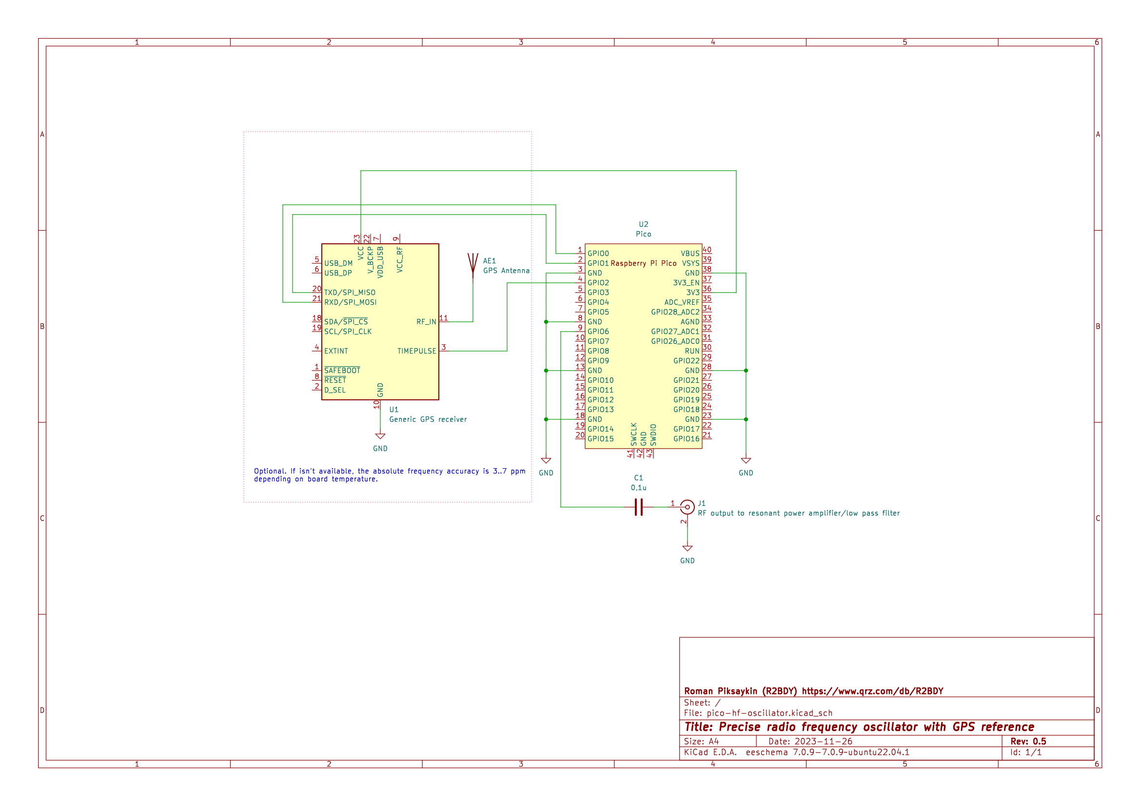
# GPS reference frequency correction (optional) since v.0.9
|
|
GPS reference frequency correction option provides an absolute frequency error within about ~1Hz in long term.
|
|
|
|
|
|
|
|
# Dual-core
|
|
The DCO uses extensively the secodary core of the pico. The first one is for
|
|
your ideas how to modulate the DCO to obtain a desired signal.
|
|
The DCO does *NOT* use any floating point operations - all time-critical
|
|
instructions run in 1 CPU cycle.
|
|
|
|
# Radio transmitters
|
|
Owing to the meager frequency step, it is possible to use 3, 5, or 7th harmonics
|
|
of generated frequency. The practical resolution will be quite the same - far
|
|
below 1 Hz. Such solution completely cover all HF and low band up to 65.8 MHz.
|
|
|
|
# Tests of RF spectrum quality
|
|
Sweep (5Hz step, carrier is 9.4MHz) test: https://youtu.be/nYC1VDBiz4o
|
|
Pseudorandom MFSK (5Hz step, carrier is 9.4MHz) test: https://www.youtube.com/shorts/CEPW8hwlG7k
|
|
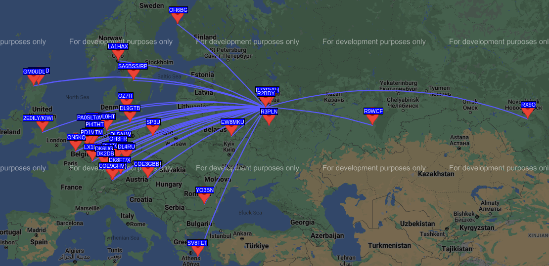
There is WSPR beacon project based on this oscillator: https://github.com/RPiks/pico-WSPR-tx
|
|
|
|
|
|
|
|
# For what?
|
|
This is an experimental project of amateur radio hobby and it is devised by me
|
|
in order to experiment with QRP narrowband digital modes.
|
|
I am licensed radio amateur who is keen on experiments in the area of the
|
|
digital modes on HF.
|
|
My QRZ page is https://www.qrz.com/db/R2BDY
|
|
|
|
|
|
|
|
# Feedback
|
|
I appreciate any thoughts or comments on that matter.
|
|
I strongly appreciate if you use this project as a part of your one in accordance with the Licence.
|
|
I have plans of building a transceiver on the base of this library.
|
|
The WSPR beacon is working and available here: https://github.com/RPiks/pico-WSPR-tx
|
|
|
|
# Quick-start
|
|
1. Install Raspberry Pi Pico SDK. Configure environment variables. Test whether
|
|
it is built successfully.
|
|
|
|
2. git clone this repository. cd pico-hf-oscillator ; ./build.sh
|
|
Check whether output file ./build/pico-hf-oscillator.uf2 appears.
|
|
|
|
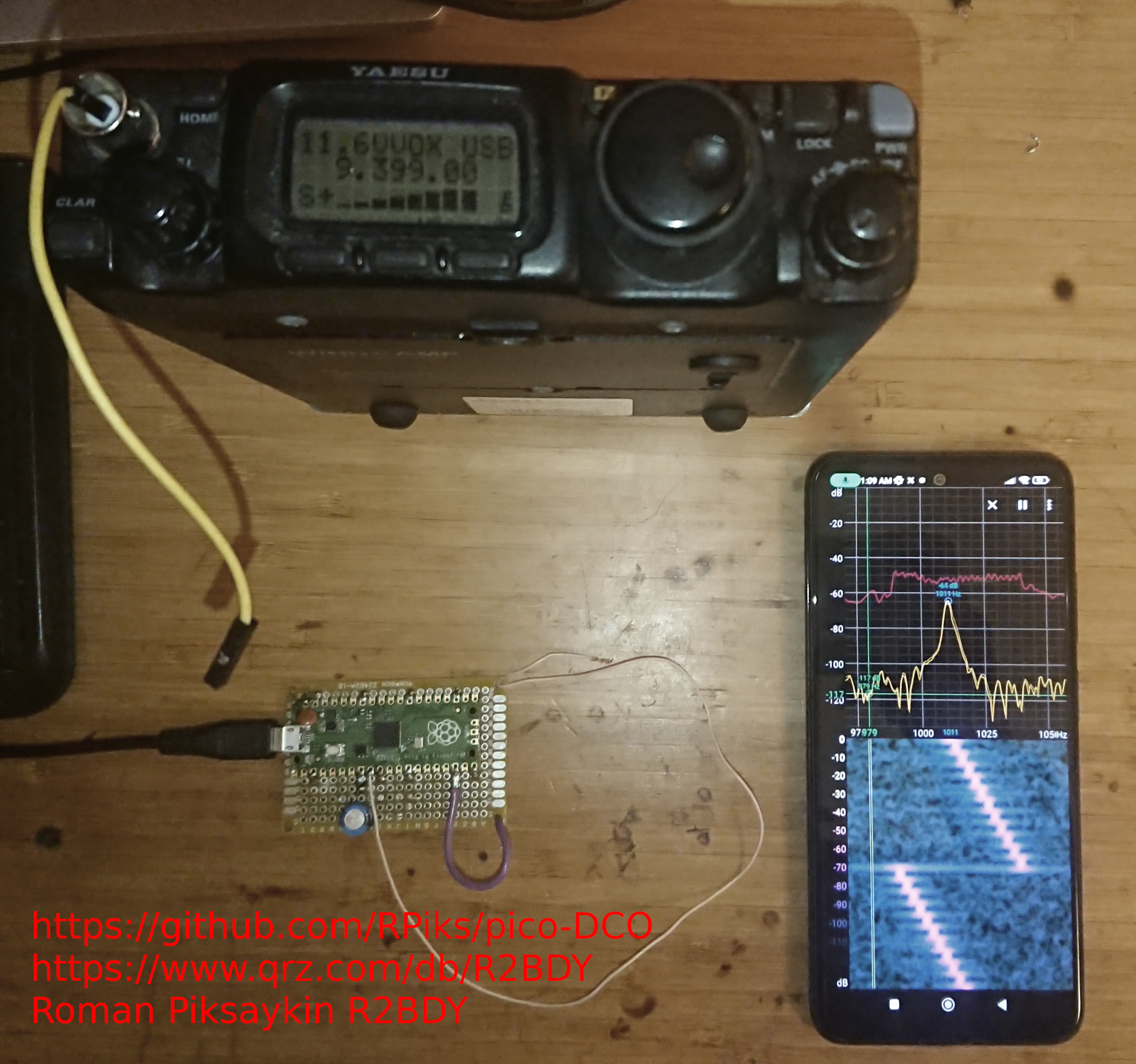
3. Prepare the surrogate antenna (if you possess an SSB receiver) or pin-out
|
|
for an oscilloscope or a spectrum analyser. The default output pin is GPIO6.
|
|
|
|
4. Load the .uf2 file (2) into the Pico.
|
|
|
|
5. Initialy the running frequency is 9.4 MHz.
|
|
|
|
6. Set any other frequency ranging from 1.1 to 9.4 MHz by #define GEN_FRQ_HZ and build the project.
|
|
|
|
7. Provide the feedback by clicking like on the github page of the project.
|
|
|
|
|
|
Cheers,
|
|
Roman Piksaykin, amateur callsign R2BDY
|
|
https://www.qrz.com/db/R2BDY
|