|
|
||
|---|---|---|
| img | ||
| README.md | ||
README.md
Vaisala RS-41 SGP Modification.
Radiosondes are
light weight sensor packages that are attached to weather
balloons.
They transmit live RF weather telemetry down to earth as
they rise.
One related hobby that a few people enjoy is radiosonde
chasing, which is tracking and collecting radiosondes once
they have fallen back to the earth.
Some people collect them as trophies, and others like to
repurpose them.
Another way to
repurpose radiosondes is to reprogram the commonly used
Vaisala RS-41 radiosondes into being able to transmit radio
APRS, 4FSK, RTTY or CW mode signals in the ISM or HAM bands.
The initial modified firmware was first performed by SQ5RWU,
and then OM3BC who managed to create firmware able to
configure settings thru the serial connection off the
radiosonde.
Darkside did also modified firmware and added a very
promising demodulation mode 4FSK, which not only decrease
the package size but also has better coverage.
This firmware could be useful for anybody requiring a cheap
transmitter for their own high altitude balloon experiments.
Also it is
possible to enter the service menu of the Vaisala RS-41
Radiosonde to learn more about its operation.
- 1.1 Hardware Details
- 1.2 Needed stuff
- 1.3 RS-41
Connector
- 1.4 ST-LINK STM32 Connection
- 1.5 Orginal
Firmware and Service Menu
- 1.6 Modified Firmware
- 1.7 Program and Flashing
- 1.8 Horus-Decoder
- 1.9 OM3BC
Firmware
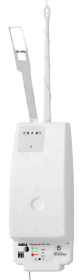
Hardware Details
The radiosonde RS41-SG was introduced by Vaisala in 2013.
On Vaisala's website it is possible to find very detailed specifications of the RS41-SG.
LED Lights operation.
Red LED:
1 - Temperature or humidity sensor broken.
2 - Low battery.
3 - Battery should be empty.
4 - Expected interface, but there is none.
Flashing Green LED:
Insufficient data for GPS
positions.
After switching on the RS41, the LED will flashes four
times.
Flashing Green LED:
1 - Turns red when something is wrong.
2 - Enable transmitter.
When the Radiosonde is flying over 100 seconds,
1 - The LED goes out.
2 - And the transmitter operates at full power.
RS-41 Details Thanks to Bazjo
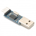
Needed Stuff
USB-TTL converter.
Some wires and connectors.
Soldering tools.
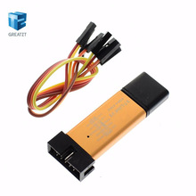
ST-LINK STM32.
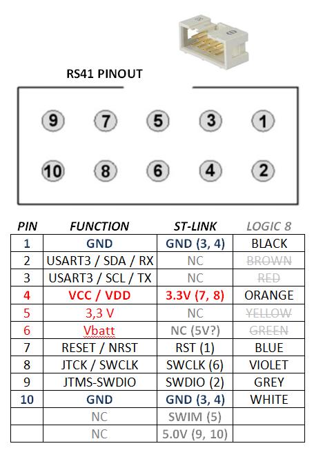
RS-41 Connector
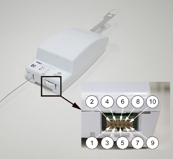
1 - GND
2 - Uart3 Rx
3 - Uart3 Tx
4 - PB1 * (10k + cap + 10k)
5 - Vcc (Boost out) 5.0V
6 VBAT 3.3V
7 - RST
8 - SWCLK
9 - SWDIO = SWID
10- GND
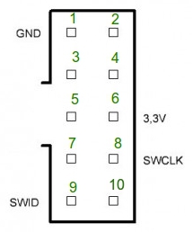
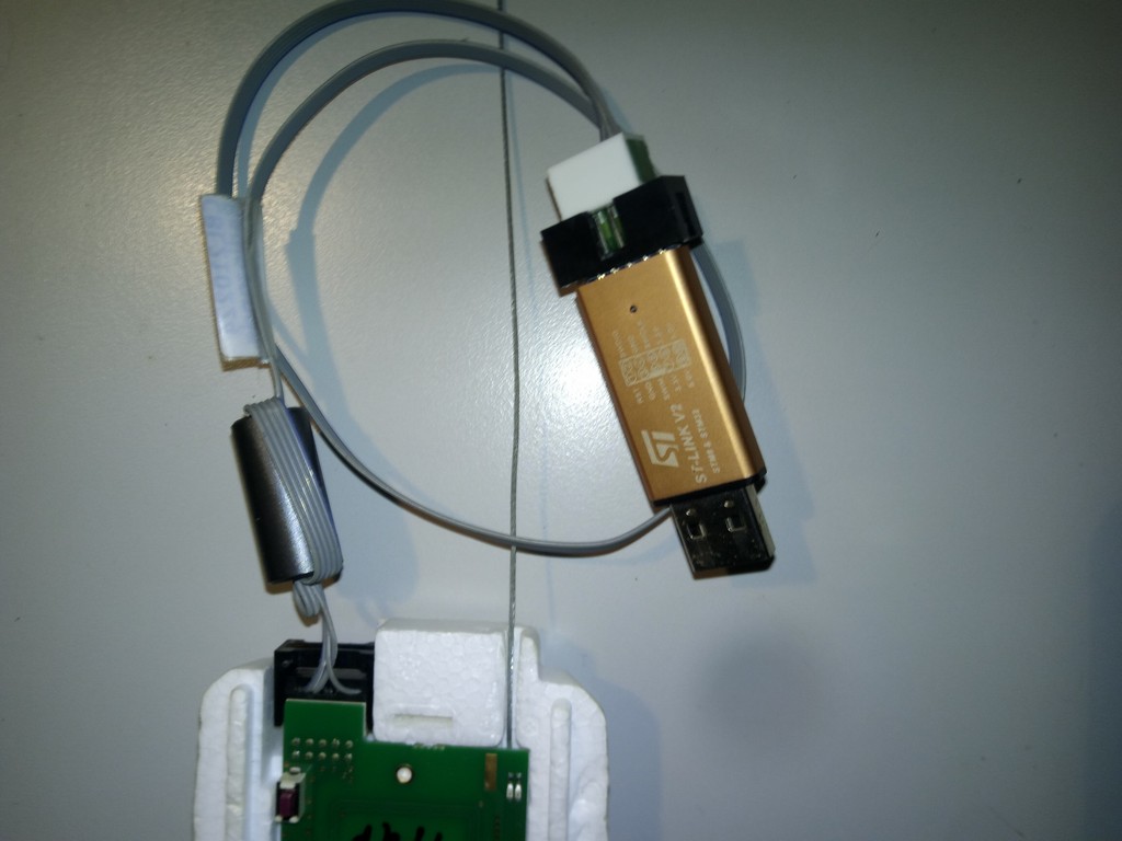
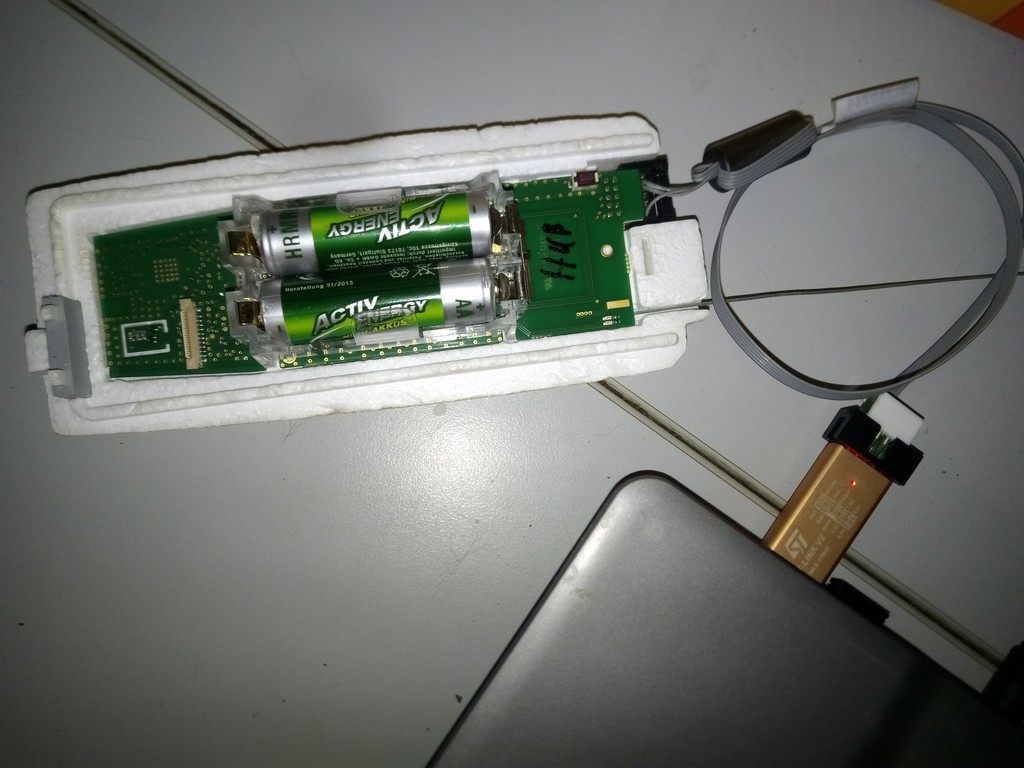
ST-Link STM32
Connection
Download ST-LINK STM32 Software http://www.st.com/en/development-tools/stsw-link004.html
Connect ST-LINK STM32:
RS41 ----- ST-LINK
===================
Pin 1 ----- GND
Pin 8 ----- SWCLK
Pin 9 ----- SWDIO = SWID
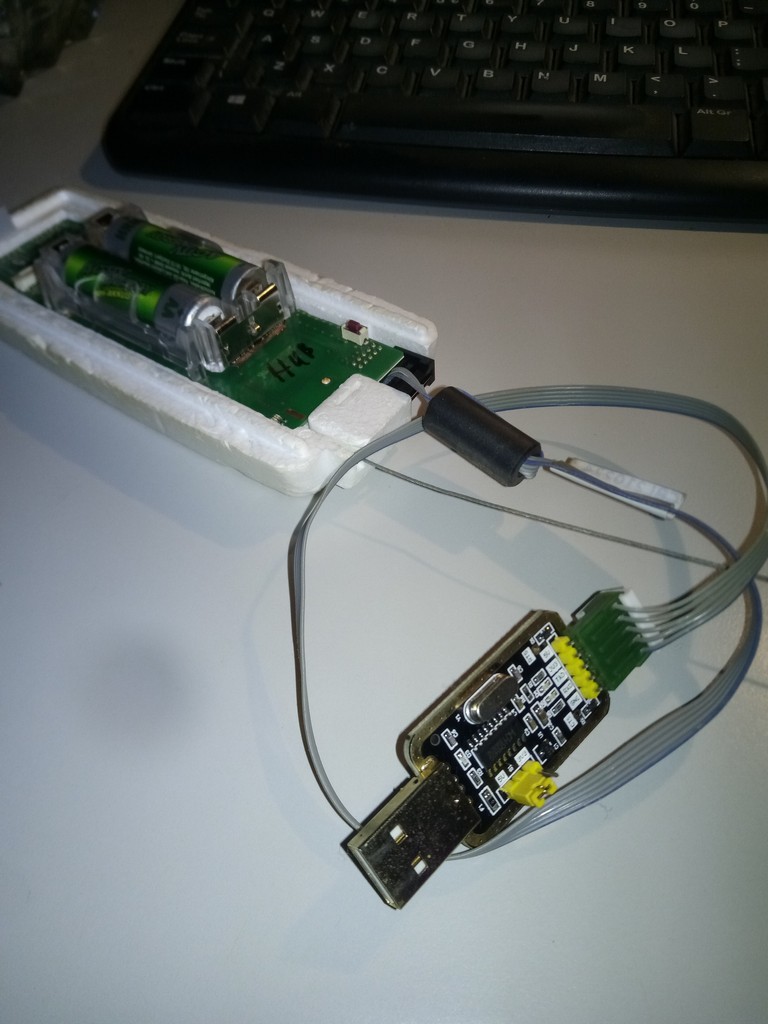
Orginal Firmware and Service Menu
Pin 1 ----- GND
Pin 2 ----- TxD
Pin 3 ----- RxD
Pin 4 ----- 3.3V
Or:
Build together ->
Connect a terminal (9k6 8N1) to the XDATA UART port.
Select COM Port (most probaly Prolific driver is needed on Windows) .
Start (hyper)terminal like Putty and connect to serial COM Port and use 9600 Baud.
Power on RS-41, Welcome message should appear with information about software version, serial number, etc:
Vaisala RS41 Radiosonde SW
V2.02.14
Copyright (c) Vaisala Oyj 2016. All rights
reserved.
Serial number: P1234567
Pressure module serial number: Px SW
V2.01
Transmitter frequency: 403.90
MHz
Transmitter power:
3/7
Enabled TX
Now enter the following five characters and press Enter :
STwsv
Press ENTER again and you should see a service menu.
Where you can change the TX power, frequency and more
options.
(S)ensors Fre(q)uencies (P)arameters (A)lfa TX p(o)wer
TX (f)requency T(X) state (T)X registers TX contin(u)ous TX ran(d)om
TX (c)arrier (B)aud rate Ser(i)al no (R)ed LED info (N)o menu
(K)eep test mode S(W) version (M)easurements (L)aunch/Drop (E)xit
>Enabled TX
A few examples:
X Transmission of the data is stopped.
o Change power level 0 - 7.
f Change Frequency.
i Change Serial Number
K Keep test mode, with this setting you do not have to re enter the pw again in order to show the service menu.
M Measurements show the following menu:
(S)ensors Fre(q)uencies S(W) reset (D)efault params (U)se sensor
(R)eg offset Reg (c)heck (T) self-check St(o)p sequence (H)eat ref
(G)PS (N)MEA D(I)rect GPS mode (E)xit
D Direct GPS mode, with option the RS-41 can be used as a GPS mouse sending True NMEA bidirectional data via UART, you can also send "N" then just NMEA is output.
Unfortunately, the settings are not retained after a power cycle.
The (T)X Registers menu option allows reading and writing of arbitrary register values.
However, these changes are not persistent, and get overwritten on startup, and whenever the transmitter is disabled and re-enabled.
The (T)X register menu is used by entering:
Txx\r (where xx is the register value in hex)
You get a prompt as follows:
>T
Register number (00-7F) >77
Register value E3 >
At this point you can either send a \r to exit back to the main menu, or you can enter a value in hex + \r which will be written to that register.
Example RS41 onto the 70cm band (434.650 MHz) by programming the following values:
0x75: 61
0x76: 10
0x77: D3
A very handy online Calculator for more Frequencies is overhere.
P (parameters):
Data ID is a hexadecimal number.
The value does not seem to have any meaning other than being used as a selector.
Values are strings or decimal numbers.
ID card Value Changeable Note:
10 5 *
20 14 *
30 0 *
40 0 *
45 S0341201 * Serial number
50 RS41-SG * RS41 model
60 20215 --- Firmware Version (V2.02.15)
70 9089 *
80 4 ---
90 5 ---
A0
B0
C0
D0 600 * Height [m] above the launch site that the RS41 must
climb to before entering flight mode.
E0 18 * Low battery voltage threshold [100 mV] below which
the probe will turn off (if the condition persists for some
time). 18 = 1.8V
100180
110 60
120 1700
130 20
140135
150 50
160 1
170 RSM412 PCB type
180 R4550425 PCB serial
190 0000000000
1A0
1A8
1B0
1B8
1C0
1C8
1D0
1D5
1D8
1E0
200 29 --- Current battery voltage [100 mV]. 29 = 2.9 V.
210 0 ---
220 41 --- Current CPU temperature [° C]
230 48 --- Current radio temperature (Si4032) [° C]
240 1 ---
250 42 --- Current temperature reference range [° C]
255
260
Modified Firmware
There are a few different firmware's each with their
advantages.
1: 70cm Band, GPS and telemetry data in RTTY, APRS and CW on seperately defineable TX frequencies.
https://github.com/df8oe/RS41HUP
2: 70cm Band, GPS and telemetry
data in CW, RS41-FOX - RS41 Amateur Radio Direction Finding
(Foxhunting) Beacon
This codebase turns a Vaisala RS41 into a 70cm 'radio fox',
suitable for use in amateur radio direction finding
contests.
https://github.com/darksidelemm/RS41FOX
Features:
Morse Ident containing callsign
& current battery voltage.
Long CW beacon (user-defined length and number of repeats)
Low-Voltage Cutout, to avoid destroying rechargable
batteries.
Beacon GPS position when battery is below a user-defined
threshold.
3: 70cm Band, GPS and telemetry
data in 4FSK and RTTY.
Information
on the 4FSK mode's performance.
Recommend for short and long HAB
floater flights.
Features:
Powersave modes for Radio:
Then the transmitter will turn off between transmissions,
saves about 50mA of power consumption.
GPS in PowerSave Mode,
Transmitting @ 13 dBm = ~120 mA, not Transmitting = 30-50mA,
depending on GPS state.
Deep Sleep Mode intended for
long duration flights only!
Power consumption in sleep mode = 32mA @ 3V
In this mode, the GPS is turned into a sleep mode in between
transmissions.
During this sleep period, we sent one 'pip' every few
seconds.
At the end of the sleep period, the GPS is powered back up,
and we await the GPS to obtain a fix before transmitting our
position.
While waiting for GPS lock, we send a 'double pip'.
Tracking sonde position from
habhub.
https://github.com/darksidelemm/RS41HUP
Settings and Config (edit in
config.h) for this software must be written before flashing.
Grab the latest GNU ARM Embedded toolchain from here: https://developer.arm.com/open-source/gnu-toolchain/gnu-rm/downloads
Extract the tarball to ~/opt/
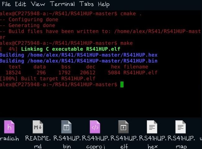
Within the RS41HUP directory:
Edit CMakeLists.txt and set the correct path to the un-tar'd
directory.
cmake .
make
Note:
For your own flights, you will need to request a payload ID.
Payload IDs can be requested by either raising an Issue, or a Pull Request on https://github.com/projecthorus/horusdemodlib/
Change the payload ID in config.h#define BINARY_PAYLOAD_ID 0 // Payload ID for use in Binary packets
Use the newly created bin or hex file to flash the RS-41.
Program and
Flashing
Connect RS-41 and power on.
Open ST-Link Utility:
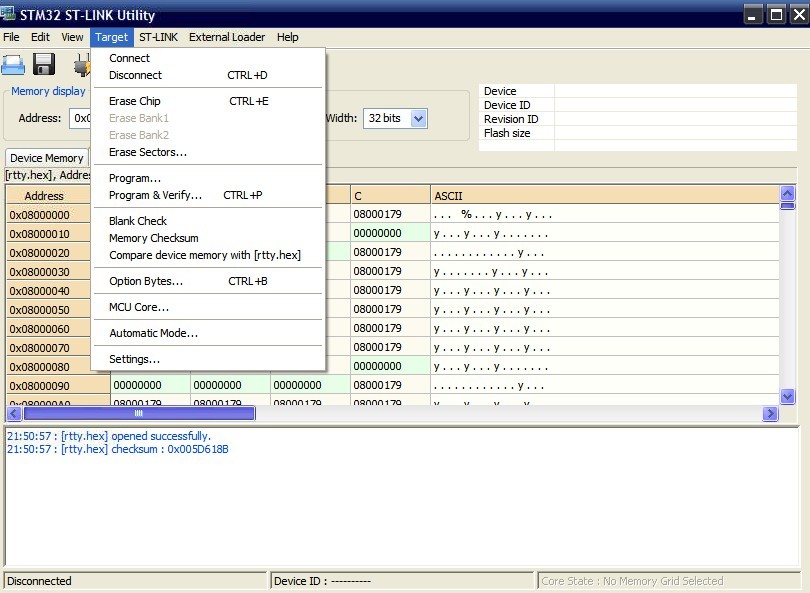
Load bin or hex file.
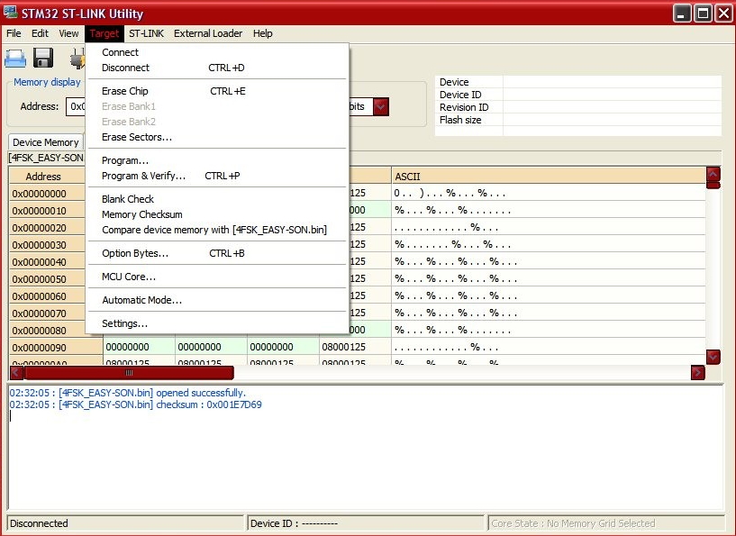
In target menu select Connect.
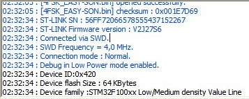
This message can happen:
Can not read memory!
Read out protection is activated
Disable Read Out Protection and retry.
In the target menu/option bytes/ disable bytes read out
protection.
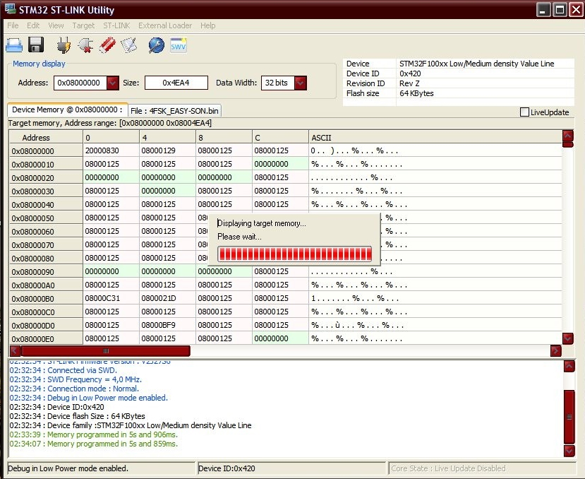
Target menu select Program and wait for flash to finish and disconnect.
Disconnect RS-41 and ST-LINK STM32.
Horus-Decoder
Telemetry demodulator for the following modems in use by Project Horus and RS-41 4FSK Modified Firmware
Horus Binary Modes (4FSK)
v1 - Legacy 22 byte mode, Golay(23,12) FEC
v2 - 16/32-byte modes, LDPC FEC (Under development)
RTTY (7N1, 7N2 and 8N2, standard UKHAS sentences with CRC16 only)
Windows builds overhere
Linux decoder for the 4FSK mode is available overhere
Flash RS-41 with 4FSK Modified Firmware
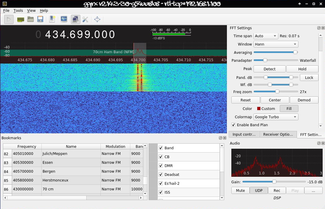
Tune in with any SDR Application (or the Horus rtl_fm scripts) on the frequency specified in config.h in USB Mode.
Start Horus-gui decoder:
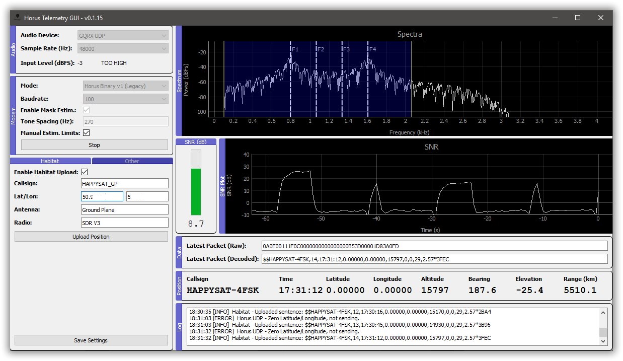
Select audio device (in this example YDP thru GQRX is used).
Mode RTTY of 4FSK, check mark for data feed to habhub upload.
Output is also possible with UDP thru Chasemapper.
OM3BC Firmware
70cm Band, GPS and telemetry data in RTTY, APRS and CW on seperately defineable TX frequencies,
configurable settings thru terminal serial connection from the radiosonde.
Hex file for flashing from om3bc.com
Recommend for playing with the Radiosonde but not for real flight's GPS outage occur for shorts periods during flight.
APRS callsign bugs.
Start (hyper)terminal like Putty and connect to serial COM Port and use 9600 Baud.
Power on RS-41, Welcome message should appear: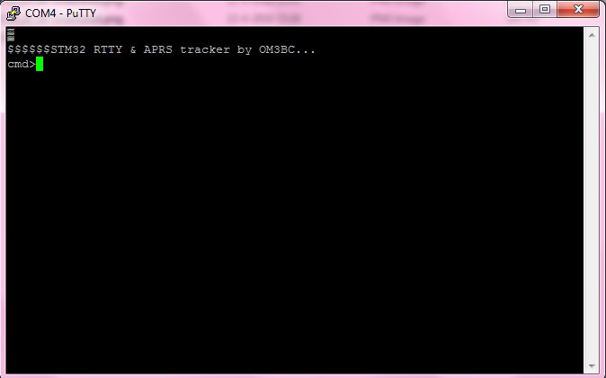
$$$$$$ STM32 RTTY
& APRS tracker by OM3BC ...
cmd>
Allowed commands
(not case sensitive):
BUTTON ON / OFF - use button to turn off /
this parameter specifies whether the push
button can be used to turn off the radiosonde
or not.
LEDs on / off - use LEDs / you can save energy
when you do not use LEDs. After switching on,
the LEDs always work, but when set to OFF,
they automatically turn off after 10 minutes
of operation.
POWER n - rf power n = 1 to 7 (7 is max.) /
output power setting 0 = smallest, 7 = maximum
power (approx. 40 mW).
APRSFRQ n - n = aprs frequency in kHz / APRS
frequency (recommended frequency is 432,500
MHz)
RTTYFRQ n - n = rtty frequency in kHz / RTTY
frequency. This frequency is also valid for CW
identification.
APRSCALL string - aprs callsign (up to 6
characters)
RTTYCALL string - rtty callsign (up to 15
characters)
CWIDMESS string - cw message (up to 25
characters)
RTTY on / off - send rtty message
HOLDOFF n - n = time between two rtty messages
in seconds
BAUD n - n = rtty baudrate
DBITS n - n = rtty databits (7 or 8)
SBITS n - n = rtty stop bits (1 or 2)
SHIFT n - n = 1,2,3,4 1 = 270, 2 = 540, 3 =
810, 4 = 1080 Hz
TEMP on / off - send temperature in rtty
messages / (The value is the temperature of
the radio chip, not the environment.)
ALT on / off - send altitude in rtty &
aprs messages
SPEED on / off - send speed in rtty messages
COURSE ON / OFF - send course in rtty messages
UBAT on / off - send battery voltage in rtty
messages
USYS on / off - send system voltage in rtty
messages / This is a constant value for
testing only.
SAT on / off - the number of GPS satellites
heard in rtty messages
APRS on / off - send aprs messages
SPEEDCOURSE on / off - send speed and course
in aprs messages
SYMBOL string - symbol from aprs symbol table
(2 characters) / two characters that determine
how the radiosonde appears on the www.aprs.fi
website.
SSID n - aprs ssid n = 1 to 15 / the caller ID of
the APRS.
TXD n - Tx delay n = 10 to 500
MICE on/off - send coded aprs messages in
mic-e format
TELEMETRY on/off - send telemetry data in aprs
messages
APRS_EVERY n - time between aprs messages is n
x holdoff / APRS packages are not required to
be given too often. This parameter specifies
the time between the two packets.
TAIL_EVERY n - time between tail text is n x
aprs time / frequency of transmission of the
attached information text (comment field).
TTEXT string - tail text (up to 100
characters) / attached information text
(comment).
CWID on/off - send cwid messages
CWID_EVERY n - time between cw messages is n x
holdoff
CW_SPEED n n = the CW identification speed in
WPM.
IGATE on/off - monitoring aprs message via
UART / after the parameter has been enabled,
the radiosonde sends a text through the serial
port that the iGate can link to.
NMEA on/off - send MNEA GPGGA and GPRMC
messages via UART / If the parameter has been
enabled, the radiosonde sends standard NMEA
GPGGA and GPRMC text via the serial port.
DISP - shows the set parameters.
SERCOM n - speed of serial communication port
(n = 300 to 115200)
DEF - set parameters to default values.
SAVE - save parameters to flash
If you need help, you can use the HELP or the
? command.
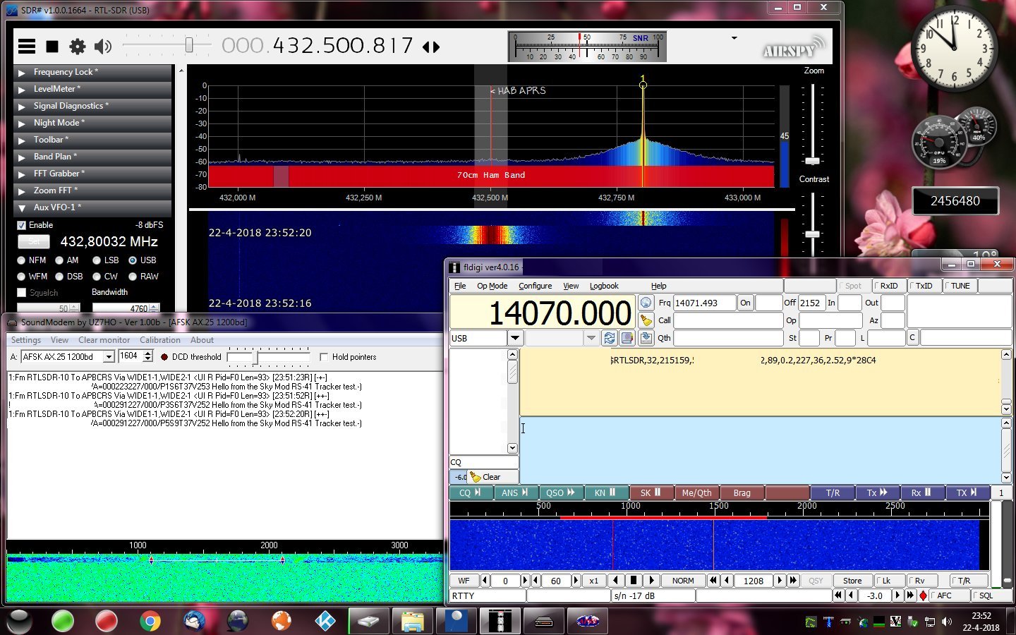
RS-41 Sending APRS Decode with Soundmodem.
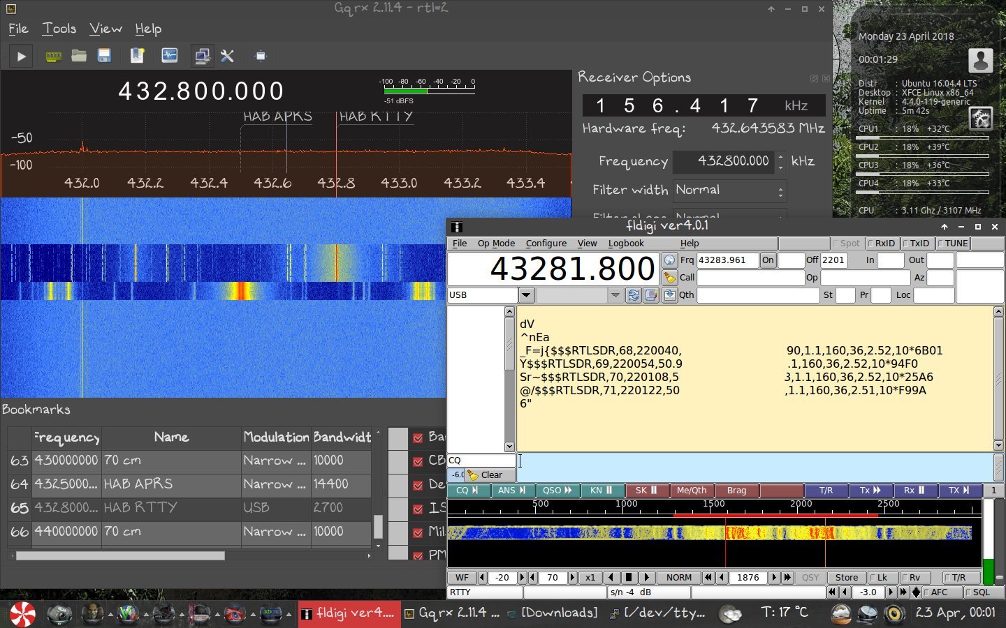
RS-41 Sending RTTY Decode with FLdigi.
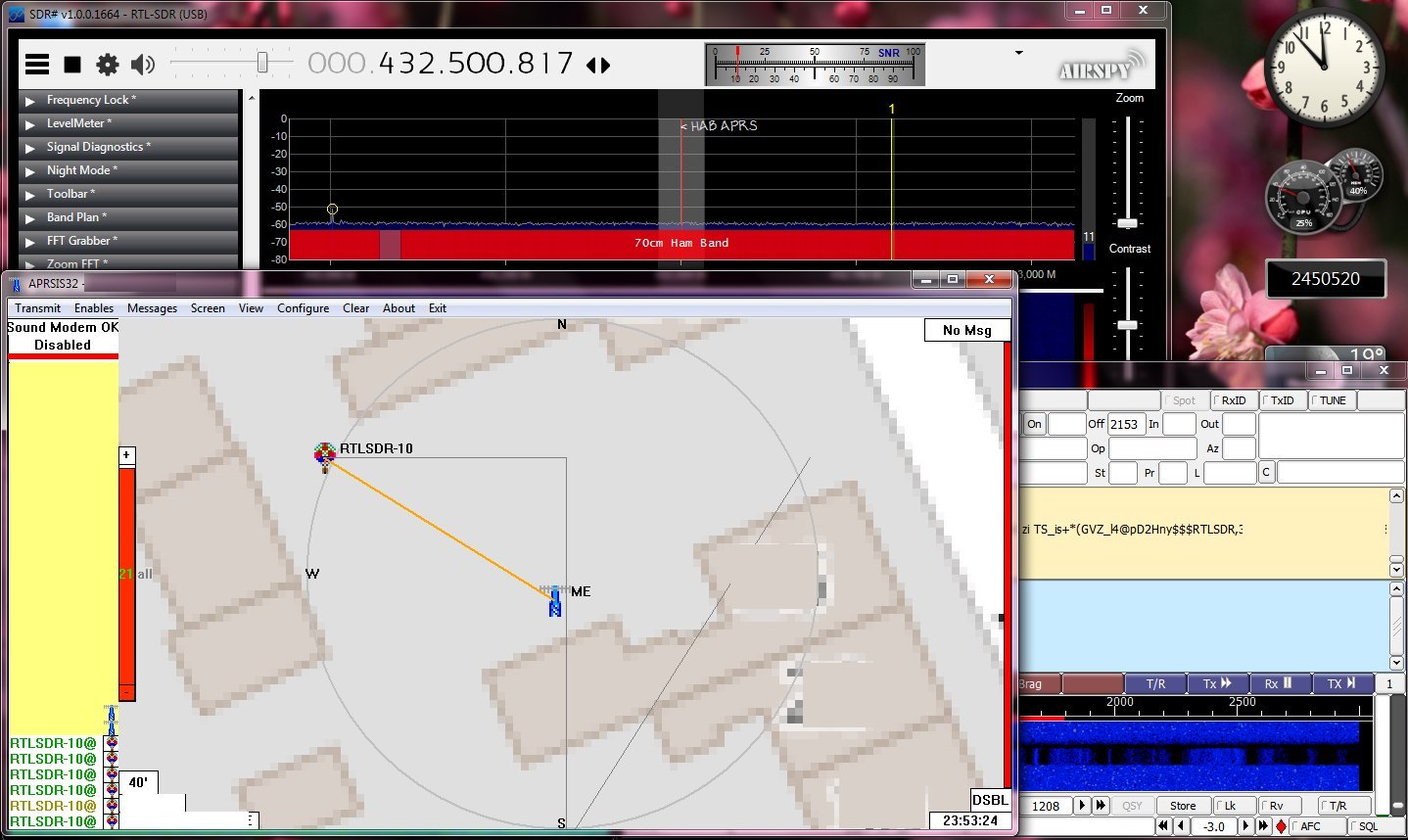
APRS Position showing in APRSIS32.
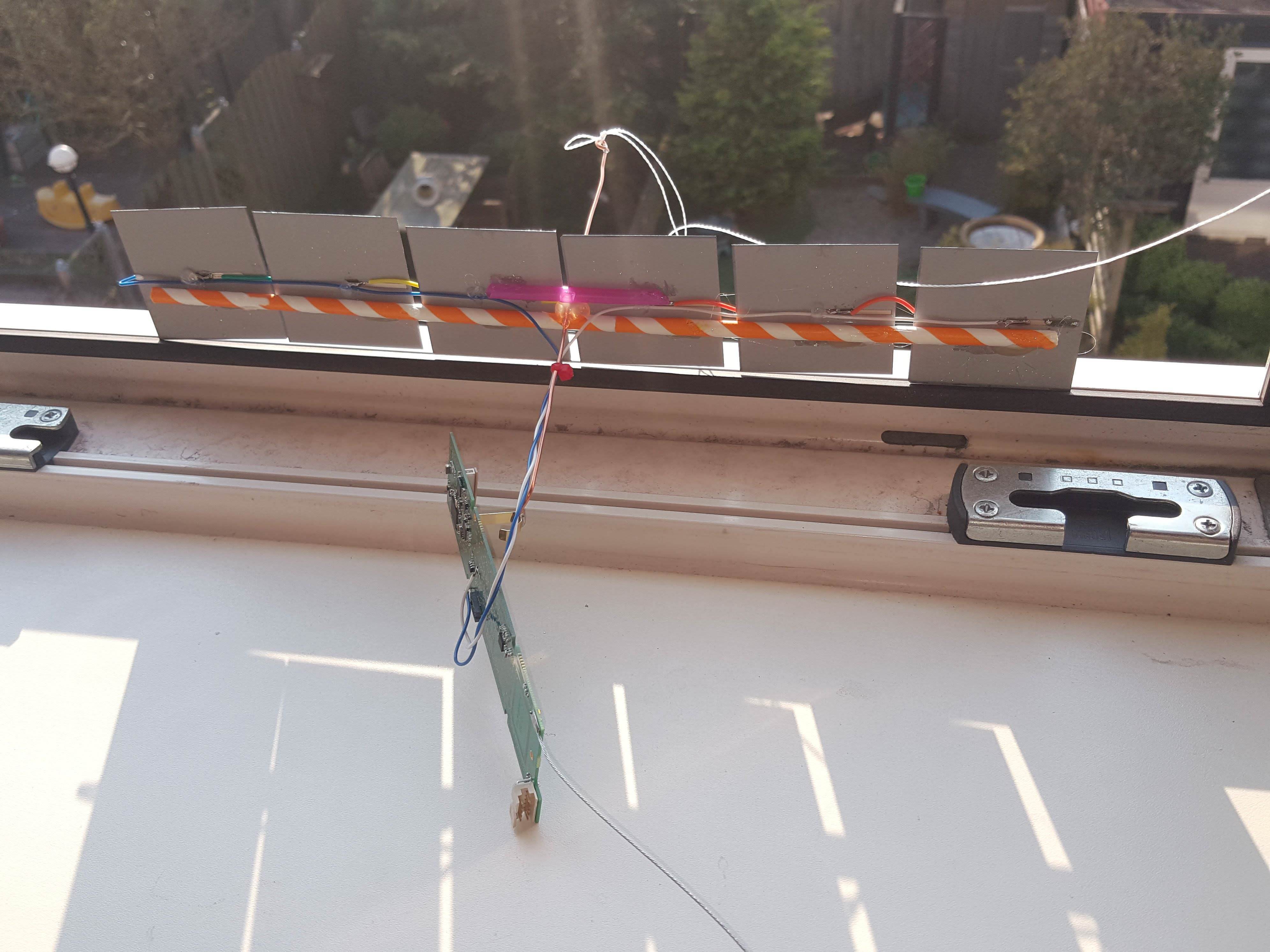
Connect it with Solar panels like PE2BZ did and launch it :)
Note:
ST-LINK STM32 / USB-TTL Converter can be found on Ali/Ebay.