12 KiB

How to build the Textile Drawing Machine

Components list
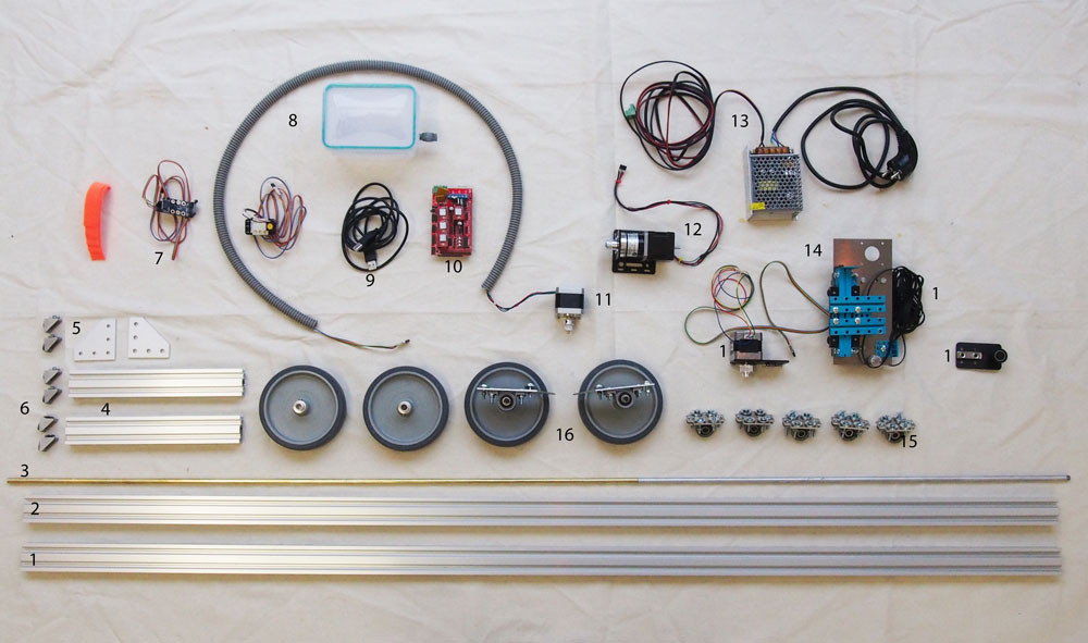
1 - Components of the X Axis made with V-Slot® NEMA 17 Linear Actuator Bundle (Belt Driven) from Openbuilds. We bought them here
2 - 1 V-Slot® 20x40x1500 mm Linear Rail. We bought it here.
3 - 1 metal rod of 8mm by 1550mm length.
4 - 2 V-Slot® 20x40x250 mm Linear Rail. We bought them here.
5 - 2 plates to reinforce the corner connections. We bought them here.
6 - 6 Cast corner brackets. We bought them. here
7 - 2 Mechanical endstops.
8 - 1 plastic tapperware to use as casing for the electronics.
9 - Cable to connect the Arduino Mega with the computer.
10 - Arduino Mega e Ramps 1.4.
11 - Hybrid Stepper Motor for 3D Printer.
12 - NEMA-17 Planetary 26.85:1 Stepper Motor
13 - Power supply 12V 5A.
14 - Z axis. See details in the following instructions.
15 - Ideally 6 ballbearings pillows unit. See details in the following instructions.
16 - 1 wheel 125mm diameter. We bought them here.
Plenty of regular nuts and bolts and plenty of Tee Nuts - M3 and plenty of low profile scrwes M5 8mm.
Part One: Z axis

1 - The actual Z axis is made of scraps found in the workshop, combining leftovers of differents machines, and it's belt driven.
We put here only some photos and not details for the contruction becuase you will never find hte same componets that we are using. Here you can find other open option for a Z Axis of this dimension.

2 - CNC alluminum cut adapter to join our Z Axis and the V-Slot Gantry Plate.
This is needed in case you are using and exhisting Z Axis or the components you have don't match the Openbuilds dimentions.
3 - V-Slot Gantry Plate with already the belt connected from the V-Slot® NEMA 17 Linear Actuator Bundle (Belt Driven).
4 - Preassure hook to fix the cable carrier.
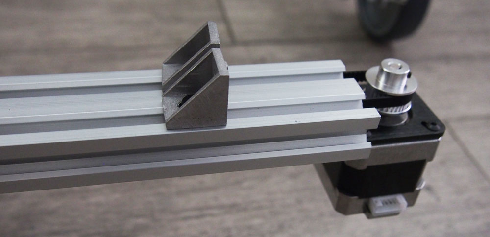
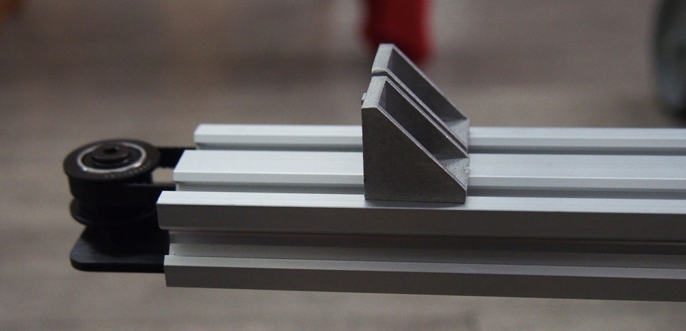
5 - Element that hit the endstop for the X Axis.
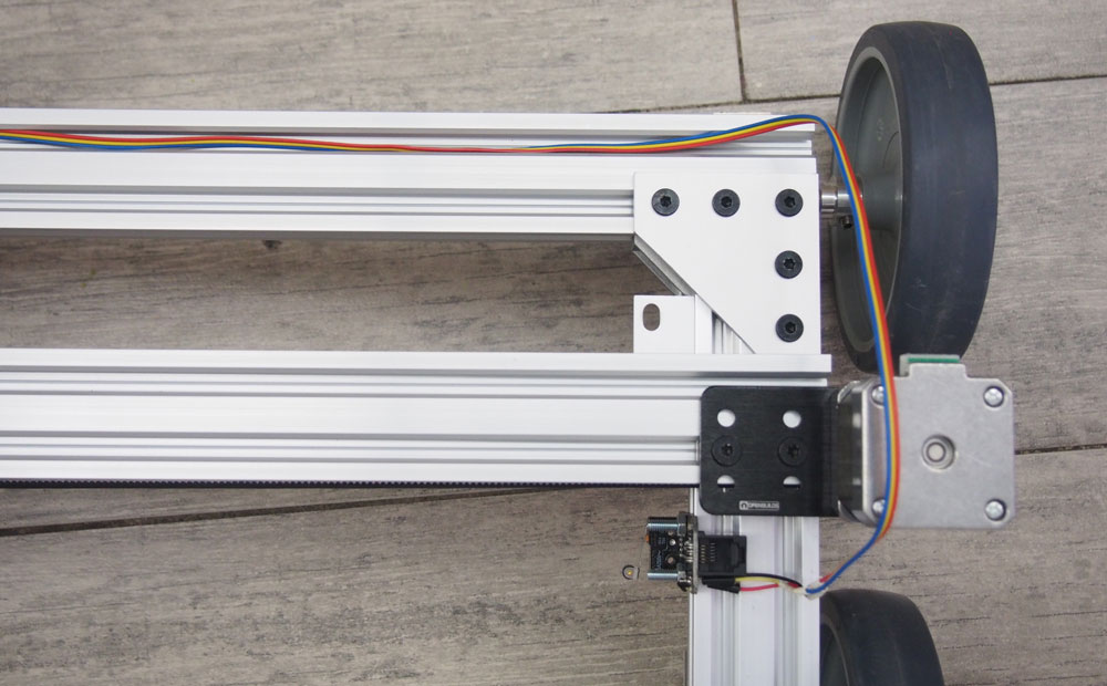
Part Two: X axis

The X Axis is an V-Slot® NEMA 17 Linear Actuator Bundle (Belt Driven) from Openbuilds. Our machine uses 1500mm V-Slot®, assembling instructions can be found here
Part Three: Y axis
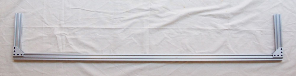
Assemble the Back frame
 1 - 1 V-Slot® 20x40x1500 mm Linear Rail. We bought it here.
2 - 2 V-Slot® 20x40x250 mm Linear Rail. We bought them here.
3 - 2 plates to reinforce the corner connections. We bought them here.
4 - 2 cast corner brackets, 14 low profile screws M5 8mm, 14 T nuts. We bought them here.
Use the cast corner brackets to connect the small linear rails to each extremities of the longer rail.
Add the joining plate to strenghten the whole structure.
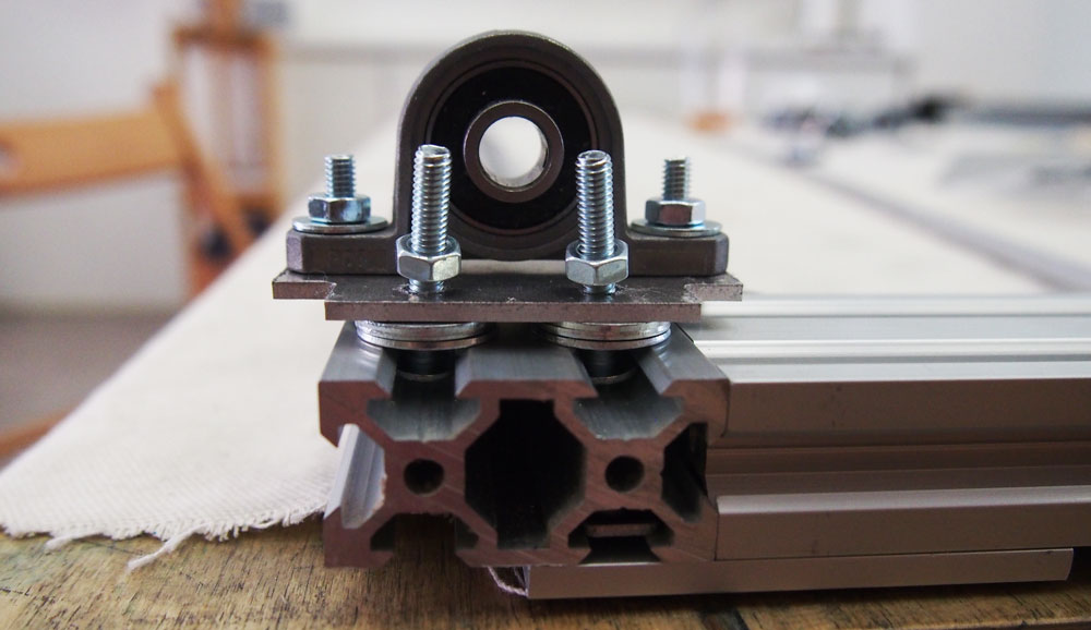
Mount the ball bearings pillows elements
Back Axle
 We reccomend to use 6 ballbearing pillows in order to keep the axle as straight as possible. Therefore repeat this for 6 times.
1 - Ball bearing pillow. We bought them Here..
2 - CNC cut aluminium adapters find file here. The adapter is needed because the standard ball bearing pillows dimensions and the vslot dimension don't fit.
3 - 6 flat head 4mm diameter screws, 14 flat washers(shims), 6 nuts.
Use 2 screws, 2 washers and 2 nuts to connect the ball bearing pillow to the adapter.
Tight firmly the ball bearings pillow using nuts.
Use 1 screw, 3 washers and 1 nut as shown in the image. (link to the pictue)
Repeat that for the remaining holes.

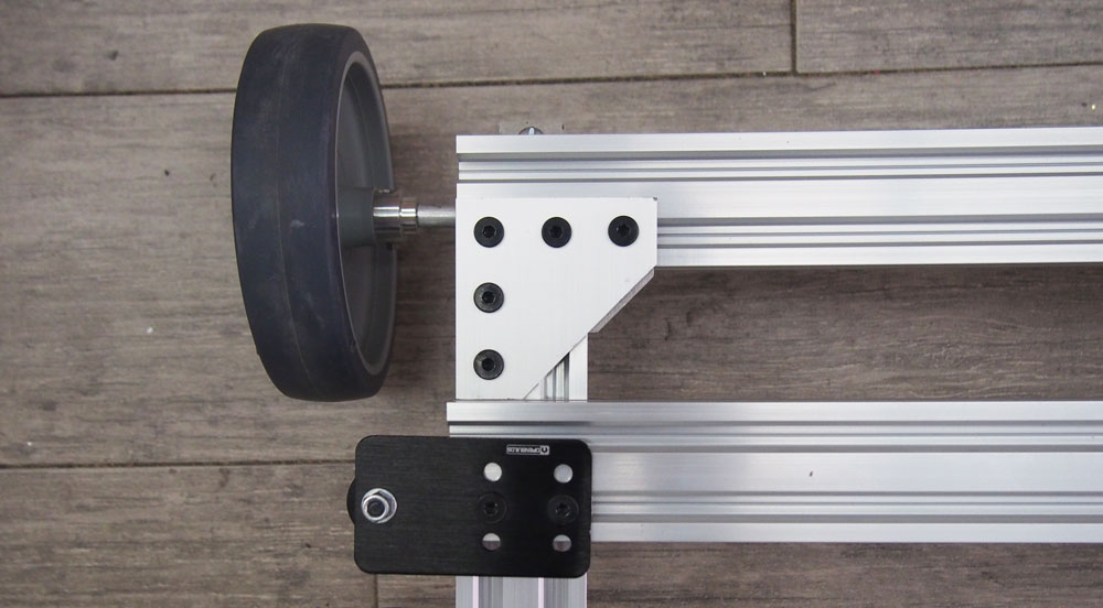
Front Axle
This is repeated for the two front wheels.

1 - 1 wheel 125mm diameter. We bought them here.
2 - 1 metal rods 8mm diameter by 15mm lenght.
3 - 2 ball bearings pillows. We bought them Here..
4 - CNC cut aluminium adapters find file here. The adapter is needed because the standard ball bearing pillows dimensions and the vslot dimension don't fit.
5 - 3 screws of 4mm diameter (used to connect the adapter onto the back frame rails), 3 nuts (used to connect the adapter onto the back frame rails, 9 washers(shims) (used to connect the adapter onto the back frame rails, 4 screws of 4mm diameter (used to fix the ball bearings pillows onto the adater, 4 nuts (used to fix the ball bearings pillows onto the adater, 4 wahsers(shims) (used to fix the ball bearings pillows onto the adater).

Mount the ball bearings pillows onto the adapter with the screws, nuts and washers. Use 1 screw, 3 washers and 1 nut as shown in the image. Do not tighten the nut onto the adapter since it will be inserted into the back frame rail. Repeat that for the other two holes as shown on the picture.
Repeat that to assemble the other unit.
Mount the Y Axis.

1 - 1 assembled back frame.
2 - 5 or 6 assembled ball bearings pillows units.
3 - 1 timing pulley GT2 Bore 8 mm - Width 6 mm, 1 timing belt GT2 Pitch 2 mm - Width 6 mm Length: 112 mm.
4 - 1 NEMA 17 Stepper Motors 1.8° 2.8V 1.68A 1:27, 1 stepper mounting bracket (NEMA 17), 1 V-slot gantry plate (20mm).
5 - 1 metal rod of 8mm by 1550mm length.
6 - 2 wheels 125mm diameter. We bought them here.
Insert into the linear rail three ball bearings pillows units.
Fix one at one edge of the rail.
The other two should be fixed at 300mm from each others.
Do not tighten the units too much since it will have to be adjusted most likely.
Insert the metal rod into the ball bearings pillows units.

Add the timing pulley and the timing belt onto the metal rods.
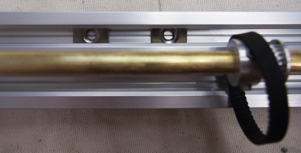 Insert into the internal rail of the back frame the 2 T nuts (this is for fixing the stepper motor)
And insert the remaining ball bearings pillows units.
Once everything is correctly inserted and the rod is rotating properly, tighten the ball bearings pillows onto the rails.
After that, tightnen the screws of the ball bearings onto the rod to fix it for good.


Screw the mounting bracket onto the v-slot gauntry plate with screws and nuts.
Assemble the stepper motor onto the mounting bracket.
Mount the timing pulley on the axis of the motor.
Fix the V-slot gauntry plate to the T nuts inserted previously onto the back frame rail.
Obvisoulsy, the pulley inserted previously onto the metal rod of the back frame and the pulley on the axis of the stepper motor needs to be aligned so that the belt can be mounted properly.

Mount the wheels onto both edges of the metal rod.
Part four: connect the X axis to the back frame
for this step, the components needed are:
- 4 cast corner brackets
- 8 low profile screws M5 8mm
- 8 T nuts
- 1 assembled X axis
- 1 assembled back frame

Insert two T nuts onto each inside rails of the short linear rails of the back frame.
Put the X axis up side down (stepper motor looking down) and insert the cast corner brackets onto the rails. There should 2 pairs of brackets facing each other.

Put the back frame onto its wheels and place the X axis and push it against the cast corners adapter of the back frame. This will ensure that the X axis is perfectly straight. Tighten the cast corner brackets of the X axis onto the T nuts previously inserted onto the back frame rails.
Part five: mount the front wheels onto the back frame
For this step, the components needed are:
- 2 already assembled front ball bearings pillows units
- 2 wheels Devantech 125mm Wheel Product Code: RB-Dev-36
Insert the assembled front ball bearings pillows units onto the small rail of the back frame. Fix them tightly at the edges of the back frame rails.

It is important to use an adapter here and not simply mount the ball bearings pillows onto the rails because the front and the back wheels need to be at the exact same height.
Wire up the electronics

1 - Power supply 12V 5A.
2 - RAMPS 1.4.
3 - Arduino MEGA.
4 - 2 mechanical endstops.
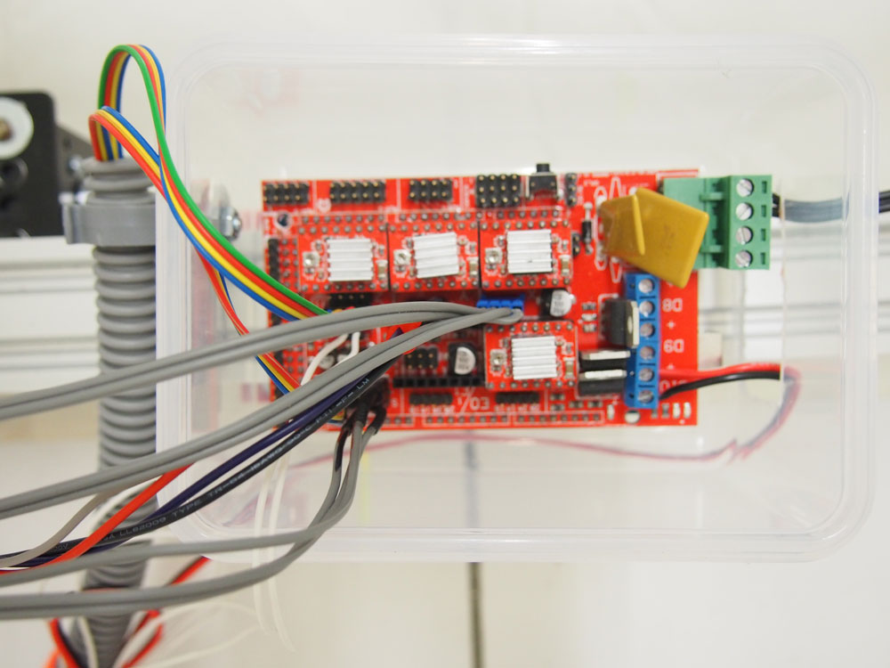
Casing for the boards
The machine is driven by an arduino MEGA and a RAMPS 1.4. In order to place the board on the machine, a custom casing can be used. The solution suggested here is to use a kitchen tupperware box.
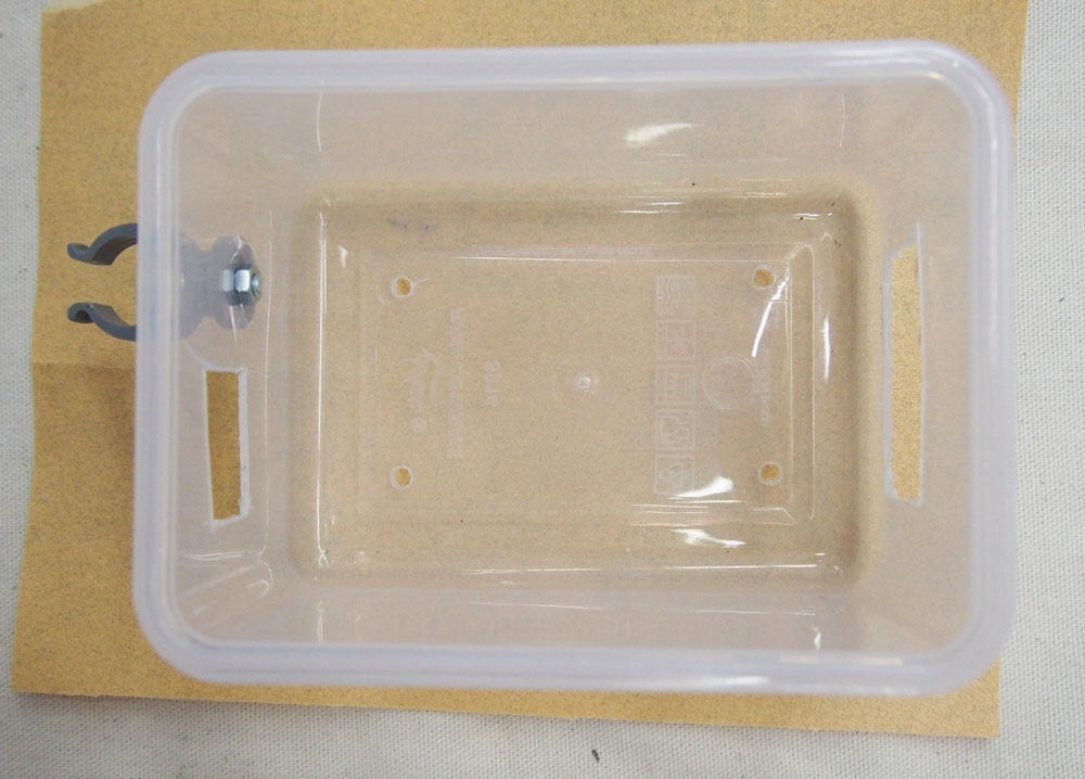
The casing is mounted into the machine back frame using tie wraps through four holes drilled on the bottom of the tupperware.
Other two holes are made on the short sides of the casing respectively to allow the power and usb cables access on one side and all the other wires on the other side.
Attention, make sure that the casing used is non conductive. Plastic is good, metal is not!!

Place the casing on the rails of the back frame and secure it using the tie wraps.
Mount the mechanical endstops
You will need to have two Mechanical endstops, one for the Xaxis and one for the Y axis. We recovered the endstops from an old plotter but you can find new one here. Each typology of endstop will be mounted in a different way.

Endstop for the Z Axis.
 Endstop for the X Axis.
Mount the Z Axis stepper motor
Because of our contruction of the Z Axis we mount only now the motor becuase of its wight.


Connect all the cables
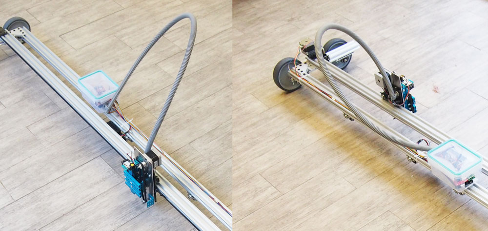
A nice way to organise the wires of the Z axis stepper motor and Z axis endstop is to passed them through some PVC corrugated tube tube, that will serve as a cable carrier . In order to fix the tube, a plastic bracket can be mounted onto the casing.
This is how the fully assemble machine looks like withouth the drawing element.