kopia lustrzana https://github.com/Xinyuan-LilyGO/TTGO-T-Display
LCD IPS ST7789V 1.14" RGB + EPS32 : https://myduino.com/product/tgo-007/
|
|
||
|---|---|---|
| 3d_file | ||
| TFT_eSPI | ||
| eagle | ||
| firmware | ||
| image | ||
| kicad/TTGO_T_Display | ||
| schematic | ||
| .gitignore | ||
| LICENSE | ||
| README.MD | ||
README.MD
TTGO T-Display
Quick start
- Install USB driver, CHxxx Series MAC driver , CHxxx Series Windows driver,CP21xx Series driver
- Copy TFT_eSPI to the <C:\Users\Your User Name\Documents\Arduino\libraries> directory
- Open Arduino IDE, find TFT_eSPI in the file and example, the T-Display factory test program is located at TFT_eSPI -> FactoryTest, you can also use other sample programs provided by TFT_eSPI
- In the Arduino IDE tool options, select the development board ESP32 Dev Module, select Disable in the PSRAM option, select 4MB in the Flash Size option, Other keep the default
- Select the corresponding serial port. If you are not sure, please remove all the serial ports, leaving the board in the USB connection state, just select that one
- Finally, click upload, the right arrow next to the tick
- Please note that the highest version currently supported by TFT_eSPI is 2.0.14. Compiling with a version higher than 2.0.14 will result in an error. Please pay attention to the selection of esp32 version.
Tools -> Board -> Boards Manage -> Search esp32 -> 2.0.14 -> Install
- 安装 USB 驱动, CHxxx Series MAC driver , CHxxx Series Windows driver, CP21xx Series driver
- 拷贝 TFT_eSPI 到 <C:\Users\你的用户名\Documents\Arduino\libraries> 目录内
- 打开ArduinoIDE , 在文件,示例中找到TFT_eSPI, T-Display出厂测试程序位于TFT_eSPI -> FactoryTest,你也可以使用其他TFT_eSPI提供的示例程序
- 在Arduino IDE 工具选项中 , 开发板选择 ESP32 Dev Module,在PSRAM选项中选择Disable, Flash Size 选项中选择4MB ,其它保持默认
- 选择对应的串行端口,如果不清楚请移除所有串行端口,之保留板子处于USB连接状态,选择那一个即可
- 最后可点击上传即可,勾号旁边的向右箭头
- 请注意,TFT_eSPI 目前支持最高版本为2.0.14 ,高于 2.0.14 编译则会报错,请注意esp32 版本的选择:
Tools -> Board -> Boards Manage ->Search esp32 -> 2.0.14 -> Install
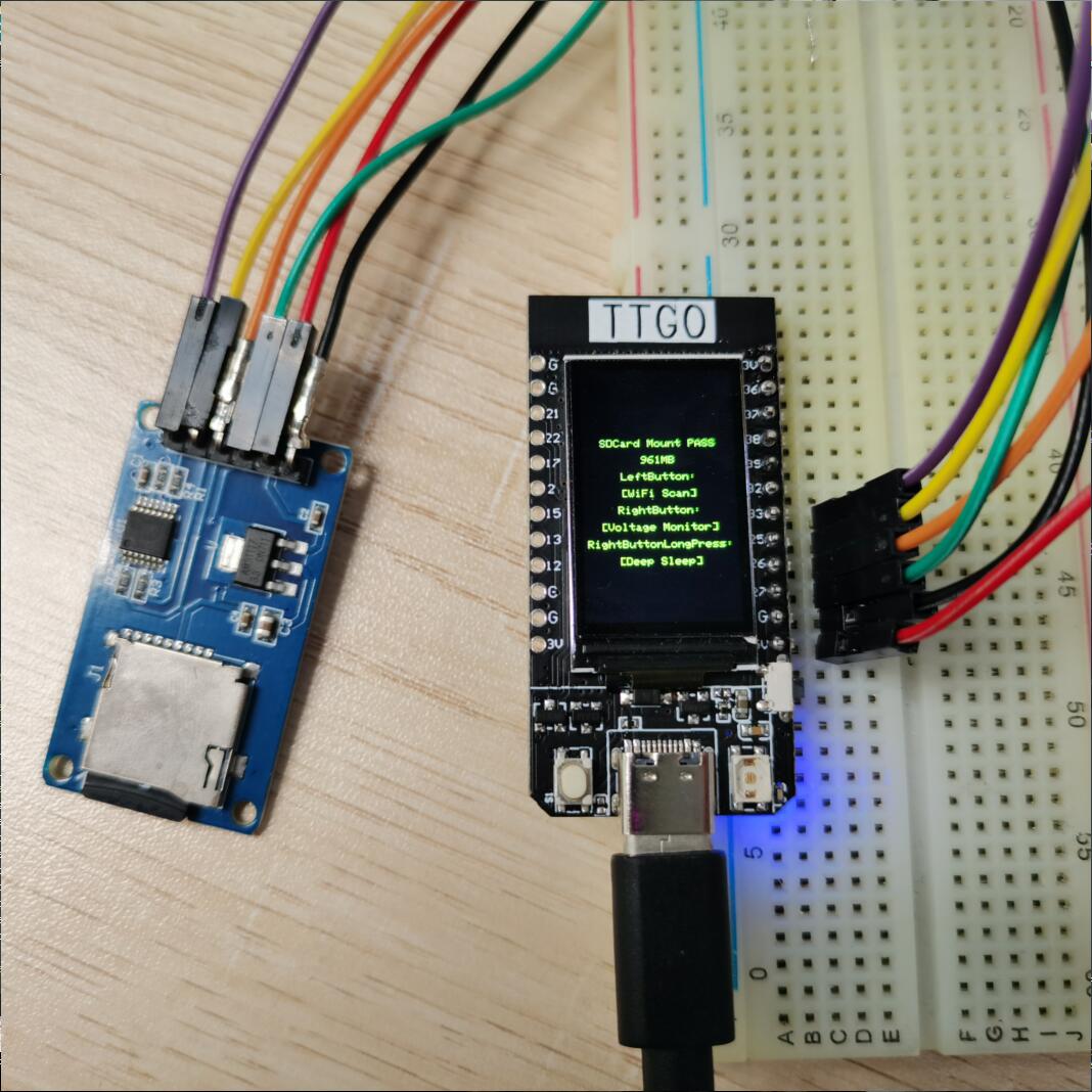
SD card connection
- Demonstrate how to use the second SPI device, using the SD card as a demonstration device
- 使用SD卡作为演示设备,演示如何使用第二个SPI设备

Pinout
| Name | V18 |
|---|---|
| TFT Driver | ST7789 |
| TFT_MISO | N/A |
| TFT_MOSI | 19 |
| TFT_SCLK | 18 |
| TFT_CS | 5 |
| TFT_DC | 16 |
| TFT_RST | 23 |
| TFT_BL | 4 |
| I2C_SDA | 21 |
| I2C_SCL | 22 |
| ADC_IN | 34 |
| BUTTON1 | 35 |
| BUTTON2 | 0 |
| ADC Power | 14 |