Notes:
The Magloop Antenna Calculator was developed to predict the characteristics of a small-loop (aka "magnetic loop" or "magloop") antenna, given physical dimensions entered via slider widgets. It assumes the main loop is made from a round anodised copper or aluminium conductor. I developed this multi-turn capable magloop calculator to take advantage of the touch-screens and high-speed of modern mobile phones, to allow users to get realtime feedback of the predicted behaviour of a magloop antenna. This would help a radio amateur to decide on the characteristics for the build.
-- 73 de VK3CPU
Inputs via the slider and radio widgets:

Change history:
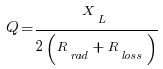
[16-Sep-21] : Updated equation used for Q to match the one use in the ARRL Antenna Book. Changed to V4. This will affect predictions for V_cap, I_loop and BW. Based on reading "Impedance, Bandwidth, and Q of Antennas" by A D Yaghjian, IEEE Transactions on Antennas and Propagation, April 2005.
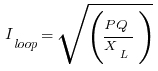
[16-Sep-21] : Added equation graphics for V_cap and I_loop formulas.
[12-Sep-21] : Set maximum values to Q, Vcap and I axes to stop autoscaling. Max Q set to 2000, Vcap to 20 kV and I to 100 A.
[12-Sep-21] : Added formula/equation graphics in Notes section. A few more complex ones, such as effective capacitance and SRF, are still needed.
[12-Sep-21] : Fixed minor error in calculation of resistive loss due to proximity effect.
[11-Sep-21] : Added visual cues for all slider-controlled parameters to highlight which parameter is being modified in the graphic representation.
[10-Sep-21] : Added c/a display to graphic representation. Moved N from center to left.
[30-Aug-21] : Added SRF calculation and display for multi-loop antennas.
[28-Aug-21] : Added support for imperial units and for aluminum metal.
[27-Jul-21] : Added total conductor length display.
[24-Jul-21] : Added loop circumference display.
The Magloop Antenna Calculator was developed to predict the characteristics of a small-loop (aka "magnetic loop" or "magloop") antenna, given physical dimensions entered via slider widgets. It assumes the main loop is made from a round anodised copper or aluminium conductor. I developed this multi-turn capable magloop calculator to take advantage of the touch-screens and high-speed of modern mobile phones, to allow users to get realtime feedback of the predicted behaviour of a magloop antenna. This would help a radio amateur to decide on the characteristics for the build.
-- 73 de VK3CPU
Inputs via the slider and radio widgets:
- ⌀a : Conductor diameter in millimeters (mm) or inches (").
- ⌀b : Loop diameter in meters (m) or feet (').
- N : Number of turns or loops.
- c/a : is the spacing ratio; based on 'c' being the inter-winding spacing for multi-turn loops measured between conductor centers, and 'a' is the conductor diameter. (Must be >= 1.1) A low-value will increase the resistance due to the proximity effect.
- Tx : The transmit power in Watts. This affects the predicted voltage across the capacitor (Vcap), and the RMS loop current (Ia).
- Metric or Imperial : selects the measuring system.
- Cu or Al : selects the type of metal conductor (annealed copper or aluminum).
- L : Inductance in microhenries.
- A : Loop area in square meters or square feet.
- C : Effective capacitance for multi-turn loops in picofarads.
- circ : Circumference of the main loop in meters or feet.
- c : Distance between windings, measured from the conductor centers in mm or inches.
- cond : Total conductor length in meters or feet.
- Tuning Cap (pF): The capacitance required to bring the loop into resonance at the given frequency. Value in picofarads.
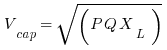
- Vcap (kV): The predicted voltage across the capacitance given the desired transmit power.
- BW (kHz): The predicted 3dB bandwidth of the magloop antenna. This is calculated from the predicted Q and the center frequency.
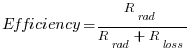
- Efficiency (%): Calculated from the radiation resistance divided by the sum of radiation resistance and the loss resistance.
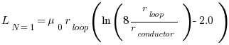
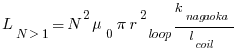
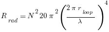
- R-radiation (Ω): The calculated radiation resistance of the loop in ohms.
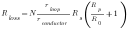
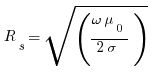
- R-loss (Ω): The calculated loss resistance of the loop in ohms, due to the combination of material conductance, skin-effect and proximity effects.
- Reactance (jΩ): The inductive reactance of the loop in ohms.
- Q : The quality factor, which is the reactance divided by the resistance of the loop at that frequency.
- Ia (A): The RMS loop current in amps.
Change history:
[16-Sep-21] : Updated equation used for Q to match the one use in the ARRL Antenna Book. Changed to V4. This will affect predictions for V_cap, I_loop and BW. Based on reading "Impedance, Bandwidth, and Q of Antennas" by A D Yaghjian, IEEE Transactions on Antennas and Propagation, April 2005.
[16-Sep-21] : Added equation graphics for V_cap and I_loop formulas.
[12-Sep-21] : Set maximum values to Q, Vcap and I axes to stop autoscaling. Max Q set to 2000, Vcap to 20 kV and I to 100 A.
[12-Sep-21] : Added formula/equation graphics in Notes section. A few more complex ones, such as effective capacitance and SRF, are still needed.
[12-Sep-21] : Fixed minor error in calculation of resistive loss due to proximity effect.
[11-Sep-21] : Added visual cues for all slider-controlled parameters to highlight which parameter is being modified in the graphic representation.
[10-Sep-21] : Added c/a display to graphic representation. Moved N from center to left.
[30-Aug-21] : Added SRF calculation and display for multi-loop antennas.
[28-Aug-21] : Added support for imperial units and for aluminum metal.
[27-Jul-21] : Added total conductor length display.
[24-Jul-21] : Added loop circumference display.