Add sizeToContents in ChannelGUI and FeatureGUI, called when widget is rolled, so we can remove resizing code from all of the individual channels and features. In RollupContents, use minimumSizeHint for calculated size, so that minimumWidth can come from .ui file. In DeviceGUI::sizeToContents(), call adjustSize(), so Device GUIs start out at minimum needed size (which should restore appearance prior to last patch). In stackSubWindows, use available space for channels if no spectrum/features present. In stackSubWindows, fix spectrum from being sized too big, resulting in scroll bars appearing. Reset user-defined channel width in stackSubWindows, when channels are removed. Don't stack maximized windows. There's one hack in Channel/FeatureGUI::maximizeWindow(). It seems that when maximimzing a window, QOpenGLWidgets aren't always paint properly immediately afterwards, so the code forces an additional update. I can't see why the first call to paintGL doesn't work. |
||
|---|---|---|
| .. | ||
| CMakeLists.txt | ||
| beamsteeringcwmod.cpp | ||
| beamsteeringcwmod.h | ||
| beamsteeringcwmodbaseband.cpp | ||
| beamsteeringcwmodbaseband.h | ||
| beamsteeringcwmodgui.cpp | ||
| beamsteeringcwmodgui.h | ||
| beamsteeringcwmodgui.ui | ||
| beamsteeringcwmodplugin.cpp | ||
| beamsteeringcwmodplugin.h | ||
| beamsteeringcwmodsettings.cpp | ||
| beamsteeringcwmodsettings.h | ||
| beamsteeringcwmodstreamsource.cpp | ||
| beamsteeringcwmodstreamsource.h | ||
| beamsteeringcwmodwebapiadapter.cpp | ||
| beamsteeringcwmodwebapiadapter.h | ||
| readme.md | ||
readme.md
Beam Steering Continuous Wave plugin
Introduction
This MIMO transmission only (MO) plugin can be used to drive a 2 channel MO device in order to produce a continuous wave signal (CW) with a control of the phase between the two streams. When the MO device is connected to a two antenna system the resulting beam can be steered in direction using the phase difference. Control is made directly in angle units.
; This was designed more as a proof of concept of multiple output plugin rather than something really useful.
Interface
The top and bottom bars of the channel window are described here
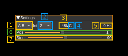
1: Channel output
The two channels A and B are connected to device output streams 0 and 1 respectively. The device must expose these channels.
Use this combo box to select channel output:
- A,B: output A and B channels
- A: output A channel only
- B: output B channel only
2: Interpolation factor
The channel sample rate is interpolated by a power of two to feed the channels at baseband sample rate.
3: Channel sample rate
This is the channel sample rate in kilo or mega samples per second indicated by the k or M letter.
4: Half-band filter chain sequence display
This string represents the sequence of half-band filters used in the interpolation from channel to device baseband. Each character represents a filter type:
- L: lower half-band
- H: higher half-band
- C: centered
5: Center frequency shift
This is the shift of the channel center frequency from the device center frequency. Its value is driven by the baseband sample rate, the interpolation factor (2) and the filter chain sequence (4).
6: Half-band filter chain sequence adjust
The slider moves the channel center frequency roughly from the lower to the higher frequency in the device baseband. The number on the right represents the filter sequence as the decimal value of a base 3 number. Each base 3 digit represents the filter type and its sequence from MSB to LSB in the filter chain:
- 0: lower half-band
- 1: centered
- 2: higher half-band
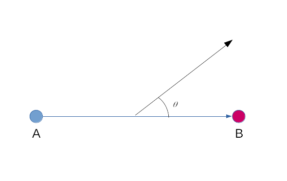
7: Steering angle
This slider controls the beam steering angle θ in degrees when the configuration of antennas is made like this: