readme.md
FunCube Dongle Pro input plugin
Introduction
This input sample source plugin gets its samples from a FunCube Dongle (FCD) Pro device.
Interface
The top and bottom bars of the device window are described here
1: Common stream parameters
1.1: Frequency
This is the center frequency of reception in kHz.
1.2: Start/Stop
Device start / stop button.
- Blue triangle icon: device is ready and can be started
- Green square icon: device is running and can be stopped
- Magenta (or pink) square icon: an error occurred. In the case the device was accidentally disconnected you may click on the icon, plug back in and start again.
1.4: Stream sample rate
Baseband I/Q sample rate in kS/s. This is the device sample rate (4) divided by the decimation factor (6).
2: Local Oscillator correction
This is the correction to be applied to the local oscillator in ppm.
3: Auto correction options
These buttons control the local DSP auto correction options:
- DC: auto remove DC component
- IQ: auto make I/Q balance. The DC correction must be enabled for this to be effective.
4: Decimated bandpass center frequency position relative to the FCD Pro center frequency
- Cen: the decimation operation takes place around the FCD Pro center frequency Fs
- Inf: the decimation operation takes place around Fs - Fc.
- Sup: the decimation operation takes place around Fs + Fc.
With SR as the sample rate before decimation Fc is calculated as:
- if decimation n is 4 or lower: Fc = SR/2^(log2(n)-1). The device center frequency is on the side of the baseband. You need a RF filter bandwidth at least twice the baseband.
- if decimation n is 8 or higher: Fc = SR/n. The device center frequency is half the baseband away from the side of the baseband. You need a RF filter bandwidth at least 3 times the baseband.
5: Decimation factor
The I/Q stream from the FCD Pro ADC is downsampled by a power of two before being sent to the passband. Possible values are increasing powers of two: 1 (no decimation), 2, 4, 8, 16.
6: Transverter mode open dialog
This button opens a dialog to set the transverter mode frequency translation options. The details about this dialog can be found here
7: Set default values
Use this push button to force default reasonable values for all parameters below (8)
8: Parameters
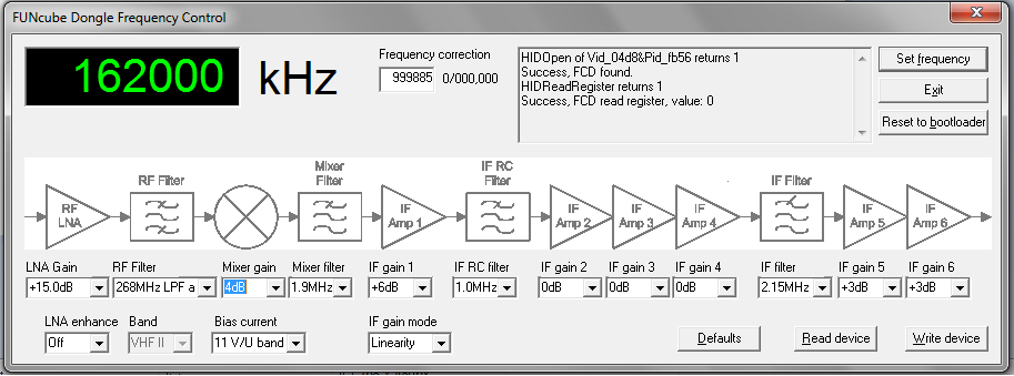
This panel lists all parameters that are the same as in the Windows utility interface showing the block diagram of the FCD:
- LNA Enh: equivalent of the "LNA enhance" parameter
- Band: equivalent of the "Band" parameter
- Bias: equivalent of the "Bias current" parameter
- Mode: equivalent of the "IF gain mode" parameter
- LNA G: equivalent of the "LNA gain" parameter
- RF filt: equivalent of the "RF filter" parameter
- Mix G: equivalent of the "Mixer gain" parameter
- Mix filter: equivalent of the "Mixer filter" parameter
- Gain1: equivalent of the "IF gain 1" parameter
- RC filt: equivalent of the "IF RC filter" parameter
- Gain2: equivalent of the "IF gain 2" parameter
- Gain3: equivalent of the "IF gain 3" parameter
- Gain4: equivalent of the "IF gain 4" parameter
- IF filt: equivalent of the "IF filter" parameter
- Gain5: equivalent of the "IF gain 5" parameter
- Gain6: equivalent of the "IF gain 6" parameter


