77 KiB
Display drivers
These drivers support nano-gui, micro-gui,
and Writer and CWriter.
They currently support four display technologies: OLED (color and monochrome),
color TFT, monochrome Sharp displays and EPD (ePaper/eInk).
All drivers provide a display class subclassed from the built-in
framebuf.FrameBuffer class. This provides three increasing levels of support:
- Graphics via the
FrameBuffergraphics primitives. - Text rendering in arbitrary fonts via
WriterandCwriterclasses (see font_to_py.py). - Use with nano-gui and micro-gui.
It should be noted that in the interests of conserving RAM these drivers offer a bare minimum of functionality required to support the above. Most drivers provide some support for bus sharing.
Users of the GUI and Writer classes only need to instantiate a display. Hence
only device constructors are documented. Other attributes are transparent to
the user. Required methods and bound variables are detailed in
Writing device drivers. Low level
access via the Writer and CWriter classes is documented
here.
Main README
Contents
- Introduction
1.1 Color handling
1.2 Installation - OLED displays
2.1 Drivers for SSD1351 Color OLEDs
2.2 Drivers for SSD1331 Small color OLEDs
2.3 Drivers for SSD1327 Greyscale OLEDs - Color TFT displays
3.1 Drivers for ST7735R Small TFTs
3.2 Drivers for ILI9341 Large TFTs
3.3 Drivers for ST7789 Small high density TFTs
3.3.1 TTGO T Display Low cost ESP32 with integrated display
3.3.2 Waveshare Pico Res Touch
3.3.3 Waveshare Pico LCD 2
3.3.4 Troubleshooting
3.4 Driver for ILI94xx Generic ILI94xx and HX8357D driver for large displays. - Drivers for sharp displays Large low power monochrome displays
4.1 Display characteristics
4.1.1 The VCOM bit
4.1.2 Refresh rate
4.2 Test scripts
4.3 Device driver constructor
4.3.1 Device driver methods
4.3.2 The vcom arg
4.4 Application design
4.4.1 Micropower applications
4.5 Resources - ePaper displays
5.1 Adafruit monochrome eInk Displays
5.1.1 EPD constructor args
5.1.2 Public methods
5.1.3 Events
5.1.4 Public bound variables
5.1.5 FeatherWing Wiring
5.1.6 Micropower use
5.2 Waveshare eInk Display HAT Pi HAT repurposed for MP hosts.
5.2.1 EPD constructor args
5.2.2 Public methods
5.2.3 Events
5.2.4 public bound variables
5.3 Waveshare 400x300 Pi Pico display Excellent display can also be used with other hosts.
5.3.1 Constructor args
5.3.2 Public methods
5.3.3 Events
5.3.4 Public bound variables
5.3.5 The Greyscale Driver - EPD Asynchronous support
- Writing device drivers
- Links
The Micropower use section is applicable to EPD's in general but makes specific reference to the 2.9" micropower demo.
Main README
1. Introduction
A nano-gui application specifies a driver by means of color_setup.py located
in the root directory of the target. In micro-gui hardware_setup.py does a
similar job, also specifying pins for the user controls.
A typical color_setup.py looks like this:
import machine
import gc
from drivers.ssd1351.ssd1351 import SSD1351 as SSD  # Choose device driver
pdc = machine.Pin('Y1', machine.Pin.OUT_PP, value=0)
pcs = machine.Pin('Y2', machine.Pin.OUT_PP, value=1)
prst = machine.Pin('Y3', machine.Pin.OUT_PP, value=1)
spi = machine.SPI(2, baudrate=10_000_000)  # baudrate depends on display chip
gc.collect()
# Precaution before instantiating framebuf. The next line creates the buffer.
ssd = SSD(spi, pcs, pdc, prst, 96)  # Create a display instance
The directory setup_examples contains examples for various displays. These
are named by graphics chip ID followed by host, thus ssd1306_pyb.py is for an
SSD1306 based display connected to a Pyboard. Files may be adapted and copied
to color_setup.py on the target's root. The section in this doc for the
specific display chip should be consulted for SSD constructor arguments and SPI
baudrate. The more exotic displays (Sharp and ePaper) have additional features
and requirements detailed below.
1.1 Color handling
Most color displays support colors specified as 16-bit quantities. Storing two
bytes for every pixel results in large frame buffers. Most of the drivers
reduce this to 1 byte (the default) or 4 bits per pixel, with the data being
expanded at runtime when a line is displayed. This trades a large saving in RAM
for a small increase in refresh time. Minimising this increase while keeping
the driver cross-platform involves the use of the viper decorator.
Eight bit drivers store colors in rrrgggbb. This results in a loss of
precision in specifying a color. Four bit drivers store a color as the index
into a 16 bit lookup table. There is no loss of precision but only 16 distinct
colors can be supported.
The choice of 16, 8 or 4 bit drivers is largely transparent: all demo scripts run in a visually identical manner under all drivers. This will apply to any application which uses the predefined colors. Differences become apparent when specifying custom colors. For detail see the main README User defined colors.
1.2 Installation
Please ensure that device firmware is up to date. On networked hardware a display driver may be installed as follows (example is for ST7789):
>>> mip.install("github:peterhinch/micropython-nano-gui/drivers/st7789")
The last part of the addresss (st7789) is the name of the directory holding
drivers for the display in use. In some cases the directory holds more than one
driver: these will all be installed. Unused drivers may be deleted.
On any hardware mpremote may be used on the PC as follows:
$ mpremote mip install "github:peterhinch/micropython-nano-gui/drivers/st7789"
Contents
2. OLED displays
2.1 Drivers for SSD1351
This is an OLED driver. The supported displays produce excellent images with extreme contrast and bright colors. Power consumption is low.
See Adafruit 1.5" 128*128 OLED display and Adafruit 1.27" 128*96 display.
There are four versions.
ssd1351.pyThis is optimised for STM (e.g. Pyboard) platforms.ssd1351_generic.pyCross-platform version. Tested on ESP32 and ESP8266.ssd1351_16bit.pyCross-platform. Uses 16 bit RGB565 color.ssd1351_4bit.pyCross-platform. Uses 4 bit color.
All these drivers work with the provided demo scripts.
To conserve RAM the first two use 8 bit (rrrgggbb) color. This works well with
the GUI if saturated colors are used to render text and controls.
The ssd1351_generic.py and 4 bit versions use the micropython.viper
decorator. If your platform does not support this, comment it out and remove
the type annotations. You may be able to use the micropython.native
decorator.
If the platform supports the viper emitter performance should still be good: on a Pyboard V1 the generic driver perorms a refresh of a 128*128 color display in 47ms. The STM version is faster but not by a large margin: a refresh takes 41ms. 32ms of these figures is consumed by the data transfer over the SPI interface. The 4-bit version with Viper takes 44ms.
If the viper and native decorators are unsupported a screen redraw takes 272ms (on Pyboard 1.0) which is visibly slow.
The ssd1351_16bit version on a 128x128 display requires 32KiB for the frame
buffer; this means it is only usable on platforms with plenty of RAM. Testing
was done on a Pyboard D SF2W. With the GUI this version offers no benefit, but
it delivers major advantages in applications such as rendering images.
For further information see the GUI README User defined colors.
This driver was tested on Adafruit 1.5 and 1.27 inch displays.
The color_setup.py file should initialise the SPI bus with a baudrate of
20_000_000. Args polarity, phase, bits, firstbit are defaults. Hard or
soft SPI may be used but hard may be faster.
SSD1351 Constructor args:
spiAn SPI bus instance.pincsAn initialised output pin. Initial value should be 1.pindcAn initialised output pin. Initial value should be 0.pinrsAn initialised output pin. Initial value should be 1.height=128Display dimensions in pixels. Height must be 96 or 128.width=128init_spi=FalseThis optional arg enables flexible options in configuring the SPI bus. The default assumes exclusive access to the bus withcolor_setup.pyinitialising it. Those settings will be left in place. If a callback function is passed, it will be called prior to each SPI bus write: this is for shared bus applications. The callback will receive a single arg being the SPI bus instance. In normal use it will be a one-liner or lambda initialising the bus. A minimal example is this function:
def spi_init(spi):
    spi.init(baudrate=20_000_000)  # Data sheet: should support 20MHz
Despite the datasheet I failed to get this baudrate to work even on a PCB.
A "gotcha" in the datasheet
For anyone seeking to understand or modify the code, the datasheet para 8.3.2
is confusing. They use the colors red, green and blue to represent colors C, B
and A. With the setup used in these drivers, C is blue and A is red. The 16 bit
color streams sent to the display are:
s[x] 1st byte sent b7 b6 b5 b4 b3 g7 g6 g5
s[x + 1] 2nd byte sent g4 g3 g2 r7 r6 r5 r4 r3
Contents
2.2 Drivers for SSD1331
This is an OLED driver for small displays. The supported display produces excellent images with extreme contrast and bright colors. Power consumption is low.
See Adafruit 0.96" OLED display. Most
of the demos assume a larger screen and will fail. The color96.py demo is
written for this display.
There are two versions. Both are cross-platform.
ssd1331.pyUses 8 bit rrrgggbb color.ssd1331_16bit.pyUses 16 bit RGB565 color.
The ssd1331_16bit version requires 12KiB of RAM for the frame buffer, while
the standard version needs only 6KiB. For the GUI the standard version works
well because text and controls are normally drawn with a limited range of
colors, most of which are saturated.
The 16 bit version provides greatly improved results when rendering images.
The color_setup.py file should initialise the SPI bus with a baudrate of
6_666_000. Args polarity, phase, bits, firstbit are defaults. Hard or
soft SPI may be used but hard may be faster.
SSD1331 Constructor args:
spiAn SPI bus instance.pincsAn initialised output pin. Initial value should be 1.pindcAn initialised output pin. Initial value should be 0.pinrsAn initialised output pin. Initial value should be 1.height=64Display dimensions in pixels.width=96init_spi=FalseThis optional arg enables flexible options in configuring the SPI bus. The default assumes exclusive access to the bus withcolor_setup.pyinitialising it. Those settings will be left in place. If a callback function is passed, it will be called prior to each SPI bus write: this is for shared bus applications. The callback will receive a single arg being the SPI bus instance. In normal use it will be a one-liner or lambda initialising the bus. A minimal example is this function:
def spi_init(spi):
    spi.init(baudrate=6_666_000)  # Data sheet: max is 150ns
Contents
2.3 Drivers for SSD1327
This driver was contributed by Mike Causer (@mcauser) and Philip Adamson (@Treadbrook). The displays are 4-bit greyscale. The driver converts 24-bit RGB colors to 4-bit greyscale based on the maximum brightness of the R, G, and B values. The driver should support any display using SSD1327 on I2C. Specific support is for:
The driver provides the following classes:
SSD1327_I2CGeneric driver for SSD1327 using I2C interface.SEEED_OLED_96X96Subclass for the Seeed display.WS_OLED_128X128Subclass for Waveshare display.
SSD1327_I2C constructor args:
widthIn pixels.heightIn pixels.i2cInitialised I2C interface.addr=0x3CI2C address.
The subclasses populate the width and height arguments appropriately for the supported displays.
SEEED_OLED_96X96 constructor arg:
i2cInitialised I2C interface.
WS_OLED_128X128 constructor args:
i2cInitialised I2C interface.addr=0x3CI2C address.
Contents
3. Color TFT displays
3.1 Drivers for ST7735R
This chip is for small TFT displays. Four drivers are provided. All are
cross-platform but assume micropython.viper capability. They use 8-bit or
4-bit color to minimise the RAM used by the frame buffer.
Drivers for Adafruit 1.8" display.
st7735r.py8-bit color.st7735r_4bit.py4-bit color for further RAM reduction.
st7735r144.py8-bit color.st7735r144_4bit4 bit color.
Users of other ST7735R based displays should beware: there are many variants with differing setup requirements. This driver has four different initialisation routines for various display versions. The supported Adafruit displays differ in their initialisation settings, hence the need for different drivers for the two display types. If your Chinese display doesn't work with my drivers you are on your own: I can't support hardware I don't possess.
The color_setup.py file should initialise the SPI bus with a baudrate of
12_000_000. Args polarity, phase, bits, firstbit are defaults. Hard or
soft SPI may be used but hard may be faster.
ST7735R Constructor args 1.8" display:
spiAn initialised SPI bus instance. The device can support clock rates of upto 15MHz.csAn initialised output pin. Initial value should be 1.dcAn initialised output pin. Initial value should be 0.rstAn initialised output pin. Initial value should be 1.height=128Display dimensions in pixels. For portrait mode exchangeheightandwidthvalues.width=160usd=FalseUpside down: setTrueto invert display.init_spi=FalseThis optional arg enables flexible options in configuring the SPI bus. See below.
ST7735R144 Constructor args 1.44" display:
spiAn initialised SPI bus instance. The device can support clock rates of upto 15MHz.csAn initialised output pin. Initial value should be 1.dcAn initialised output pin. Initial value should be 0.rstAn initialised output pin. Initial value should be 1.height=128Display dimensions in pixels.width=128rotation=0Pass 0, 90, 180 or 270 to rotate the display.init_spi=FalseThis optional arg enables flexible options in configuring the SPI bus. See below.
The init_spi constructor arg
The False default assumes exclusive access to the bus. It is initialised by
color_setup.py and those settings are left in place. If a callback function
is passed, it will be called prior to each SPI bus write. This is for shared
bus applications. The callback will receive a single arg being the SPI bus
instance. In normal use it will be a one-liner or lambda initialising the bus.
A minimal example is this function which caters for the case where another
program may have changed the baudrate:
def spi_init(spi):
    spi.init(baudrate=12_000_000)  # Data sheet: max is 12MHz
Contents
3.2 Drivers for ILI9341
Adafruit make several displays using this chip, for example this 3.2 inch unit. This display is large by microcontroller standards. See below for discussion of which hosts can be expected to work.
The color_setup.py file should initialise the SPI bus with a baudrate of
10_000_000. Args polarity, phase, bits, firstbit are defaults. Hard or
soft SPI may be used but hard may be faster. See note on overclocking below.
ILI9341 Constructor args:
spiAn initialised SPI bus instance. The device can support clock rates of upto 10MHz.csAn initialised output pin. Initial value should be 1.dcAn initialised output pin. Initial value should be 0.rstAn initialised output pin. Initial value should be 1.height=240Display dimensions in pixels. For portrait mode exchangeheightandwidthvalues.width=320usd=FalseUpside down: setTrueto invert display.init_spi=FalseThis optional arg enables flexible options in configuring the SPI bus. The default assumes exclusive access to the bus. In this normal case,color_setup.pyinitialises it and the settings will be left in place. If the bus is shared with devices which require different settings, a callback function should be passed. It will be called prior to each SPI bus write. The callback will receive a single arg being the SPI bus instance. It will typically be a one-liner or lambda initialising the bus. A minimal example is this function:
def spi_init(spi):
    spi.init(baudrate=10_000_000)
The ILI9341 class uses 4-bit color to conserve RAM. Even with this adaptation
the buffer size is 37.5KiB which is too large for some platforms. On a Pyboard
1.1 the scale.py demo ran with 34.5K free with no modules frozen, and with
47K free with gui and contents frozen. An ESP32 with SPIRAM has been tested.
On an ESP32 without SPIRAM, nano-gui runs but
micro-gui requires
frozen bytecode. The RP2 Pico runs both GUI's.
See Color handling for details of the implications of 4-bit color.
The driver uses the micropython.viper decorator. If your platform does not
support this, the Viper code will need to be rewritten with a substantial hit
to performance.
Use with uasyncio
A full refresh blocks for ~200ms. If this is acceptable, no special precautions
are required. However this period may be unacceptable for some uasyncio
applications. The driver provides an asynchronous do_refresh(split=4) method.
If this is run the display will be refreshed, but will periodically yield to
the scheduler enabling other tasks to run. This is documented
here. micro-gui
uses this automatically.
Another option to reduce blocking is overclocking the SPI bus.
Overclocking SPI
The ILI9341 datasheet section 19.3.4 specifies a minimum clock cycle time of 100ns for write cycles. It seems that every man and his dog overclocks this, even the normally conservative Adafruit use 24MHz and rdagger uses 40MHz. I have successfully run my display at 40MHz. My engineering training makes me baulk at exceeding datasheet limits but the choice is yours. I raised this isse. The response may be of interest.
Troubleshooting
Some Chinese modules produce garbled displays. Please try the
ILI9486 driver with the mirror
constructor arg set True. Patch and testing provided by
Abel Deuring.
Contents
3.3 Drivers for ST7789
These displays tend to be physically small with a high pixel density. The chip supports up to 240x320 displays. The Adafruit units tested are 240x240. To keep the buffer size down, the driver uses 4-bit color with dynamic conversion to 16 bit RGB565 at runtime. This uses a lookup table (LUT) enabling user defined colors. The resultant buffer size for the Adafruit displays is 28800 bytes. See Color handling for the implications of 4-bit color.
Tested display: Adafruit 1.3 inch. The Adafruit 1.54 inch has identical resolution and uses the same CircuitPython driver so can be expected to work.
The driver also supports the
TTGO T-Display.
This is an inexpensive ESP32 with a 135x240 color TFT display. See
setup_examples/st7789_ttgo.py.
Also, in landscape mode only, the
Waveshare Pico LCD 1.14 inch.
This has a hardware quirk, copy setup_examples/st7789_pico_lcd_114.py to
your setup file.
The color_setup.py file should initialise the SPI bus with a baudrate of
30_000_000. Args polarity, phase, bits, firstbit are defaults. Hard or
soft SPI may be used but hard may be faster. 30MHz is a conservative value: see
below. An example file for the Pi Pico is in setup_examples/st7789_pico.py.
ST7789 Constructor args:
spiAn initialised SPI bus instance. The chip supports clock rates of upto 62.5MHz (datasheet table 6). I have tested 60MHz. High speeds are sensitive to electrical issues such as lead lengths, PCB layout and grounding.csAn initialised output pin. Initial value should be 1.dcAn initialised output pin. Initial value should be 0.rstAn initialised output pin. Initial value should be 1.height=240Display dimensions in pixels. For portrait mode exchangeheightandwidthvalues: this ensures thatnano-guigets the correct aspect ratio.width=240disp_mode=LANDSCAPEThis arg enables portrait mode and other configurations. See below.init_spi=FalseFor shared SPI bus applications. See note below.display=GENERICThedisplayarg is an opaque type defining the display hardware. Current options (exported by the driver) areGENERICfor Adafruit displays andTDISPLAYfor the TTGO board.
Constants exported by the driver
The color_setup.py file should invoke the driver as follows:
from drivers.st7789.st7789_4bit import *
SSD = ST7789
The following constants are available:
Orientation (values for disp_mode):
LANDSCAPE Normal display, text is parallel to long axis.
PORTRAIT Text is parallel to short axis.
USD Upside down rendering.
REFLECT Mirror image rendering.
Display types (values for display):
GENERIC For Adafruit displays.
TDISPLAY For the TTGO T-Display and Waveshare Pico LCD.
PI_PICO_LCD_2 Waveshare Pico LCD 2 determined by Mike Wilson.
DFR0995 DFR0995 Contributed by @EdgarKluge
WAVESHARE_13 Waveshare 1.3" 240x240 LCD contributed by Aaron Mittelmeier
init_spi
This optional arg enables flexible options in configuring the SPI bus. The
default assumes exclusive access to the bus. In this normal case,
color_setup.py initialises it and the settings will be left in place. If the
bus is shared with devices which require different settings, a callback
function should be passed. It will be called prior to each SPI bus write. The
callback will receive a single arg being the SPI bus instance. It will
typically be a one-liner or lambda initialising the bus. A minimal example is
this function:
def spi_init(spi):
    spi.init(baudrate=30_000_000)
Display mode
This is provided mainly to support asymmetrical displays. It also enables the
Adafruit display image to be rotated. Any of the orientation constants listed
above may be applied, and multiple options may be combined using the bitwise-or
| operator.
When choosing LANDSCAPE or PORTRAIT mode it is essential that height and
width constructor args match the mode.
The following example color_setup.py is for Pi Pico and produces an upside
down portrait display.
from drivers.st7789.st7789_4bit import *
SSD = ST7789

pdc = Pin(13, Pin.OUT, value=0)  # Arbitrary pins
pcs = Pin(14, Pin.OUT, value=1)
prst = Pin(15, Pin.OUT, value=1)

gc.collect()  # Precaution before instantiating framebuf
spi = SPI(1, 30_000_000, sck=Pin(10), mosi=Pin(11), miso=Pin(8))
ssd = SSD(spi, dc=pdc, cs=pcs, rst=prst, disp_mode=PORTRAIT | USD)
Use with uasyncio
Running the SPI bus at 60MHz a refresh blocks for 83ms (tested on a Pi Pico at
standard clock frequency). If the blocking period is acceptable, no special
precautions are required. This period may be unacceptable for some uasyncio
applications. Some may use lower SPI baudrates either for electrical reasons or
where the host cannot support high speeds, and some platforms may run Python
code at a different speed.
The driver provides an asynchronous do_refresh(split=4) method. If this is
run the display will be refreshed, but will periodically yield to the scheduler
enabling other tasks to run. This is documented here.
The amount of data for SPI transfer for a 240x240 display is
240x240x16 = 921.6K bits
At a 60MHz baudrate this equates to
240x240x16/6e7=15.36ms
This suggests that about 80% of the latency results from the Python code. An
option may be to overclock.
3.3.1 TTGO T Display
Thanks to Ihor Nehrutsa who wrote much of the setup file for this device.
This is an ESP32 based device with an integrated 1.14" 135x240 pixel display based on ST7789.
It is supported by setup_examples/st7789_ttgo.py. Copy to
/pyboard/color_setup.py on the device. It produces a landscape mode display
with the top left hand corner adjacent to pin 36.
Commented-out code offers portrait mode.
URL's. More in st7789_ttgo.py
TTGO Product page
Ihor Nehrutsa's PR
Another MicroPython driver
Factory test (C)
3.3.2 Waveshare Pico Res Touch
This is a "plug and play" 2.8" color TFT for nano-gui and the Pi Pico. Users of
micro-gui will need to find a way to connect pushbuttons, either using stacking
headers on the Pico or soldering wires to its pads. The color_setup.py file
is as follows. Note the commented-out options and the Lewis Caroll nature of
the landscape/portrait constructor args. See setup_examples/ws_pico_res_touch.py.
import gc
from machine import Pin, SPI
from drivers.st7789.st7789_4bit import *
SSD = ST7789

pdc = Pin(8, Pin.OUT, value=0)
pcs = Pin(9, Pin.OUT, value=1)
prst = Pin(15, Pin.OUT, value=1)
pbl = Pin(13, Pin.OUT, value=1)

gc.collect()  # Precaution before instantiating framebuf
spi = SPI(1, 33_000_000, sck=Pin(10), mosi=Pin(11), miso=Pin(12))

# Define the display
# For portrait mode:
# ssd = SSD(spi, height=320, width=240, dc=pdc, cs=pcs, rst=prst)
# For landscape mode:
ssd = SSD(spi, height=240, width=320, disp_mode=PORTRAIT, dc=pdc, cs=pcs, rst=prst)

# Optional use of SD card.
from sdcard import SDCard
import os
sd = SDCard(spi, Pin(22, Pin.OUT), 33_000_000)
vfs = os.VfsFat(sd)
os.mount(vfs, "/fc")
The ST7789 is specified for baudrates upto 62.5MHz, however the maximum the
Pico can produce is 31.25MHz. The display uses a nonstandard pin for MISO. This
was proven to work by testing the SD card. This requires the official SD card
driver which may be found in the MicroPython source tree in
drivers/sdcard/sdcard.py. I am not an expert on SD cards. Mine worked fine at
31.25MHz but this may or may not be universally true.
3.3.3 Waveshare Pico LCD 2
Support for this display resulted from a collaboration with Mike Wilson (@MikeTheGent).
This is a "plug and play" 2" color TFT for nano-gui and the Pi Pico. Users of
micro-gui will need to find a way to connect pushbuttons, using stacking
headers on the Pico or soldering wires to its pads. The color_setup.py file
is as follows.
from machine import Pin, SPI
import gc

from drivers.st7789.st7789_4bit import *
SSD = ST7789

gc.collect()  # Precaution before instantiating framebuf
# Conservative low baudrate. Can go to 62.5MHz.
spi = SPI(1, 30_000_000, sck=Pin(10), mosi=Pin(11), miso=None)
pcs = Pin(9, Pin.OUT, value=1)
prst = Pin(12, Pin.OUT, value=1)
pbl = Pin(13, Pin.OUT, value=1)
pdc = Pin(8, Pin.OUT, value=0)

ssd = SSD(spi, height=240, width=320, dc=pdc, cs=pcs, rst=prst, disp_mode=LANDSCAPE, display=PI_PICO_LCD_2)
3.3.4 Troubleshooting
If your display shows garbage, check the following (I have seen both):
- SPI baudrate too high for your physical layout.
heightandwidthnot matching the choice ofLANDSCAPEorPORTRAITdisplay mode.
Contents
3.4 Driver for ILI94xx
This was developed for the ILI9486 but its application is more wide ranging. In addition to ILI9486 these have been tested: ILI9341, ILI9488 and HX8357D.
The ILI9486 supports displays of up to 480x320 pixels which is large by
microcontroller standards. Even with 4-bit color the frame buffer requires
76,800 bytes. On a Pico nanogui works fine, but
micro-gui fails to
compile unless frozen bytecode is used, in which case it runs with about 75K of
free RAM. An ESP32 with SPIRAM should work.
Generic display wiring
Testing was done with a Pico and an Adafruit 3.5inch display, using the following setup files: nanogui setup and microgui setup. These use the following pinout:
| Pico pin | GPIO | Display | Signal |
|---|---|---|---|
| 40 | n/a | Vbus 5V | |
| 36 | n/a | 3.3V | |
| 3,8,36.. | n/a | Gnd | Gnd |
| 9 | 6 | SCLK | |
| 10 | 7 | MOSI | |
| 11 | 8 | DC | |
| 12 | 9 | RST | |
| 14 | 10 | CS |
Please check the power requirements of the display board, which may require a 5V or a 3.3V supply. The Adafruit board can accept either.
Waveshare PI HAT wiring
Setup files are as per the generic display. The table shows the Raspberry Pi connector looking at the underside of the board with the bulk of the board to the right. It was tested with a Pi Pico.
Connections may be adapted for other MicroPython targets. The board may be powered from 5V or 3.3V: there is a regulator on board.
| Pico | L | R | Pico | ||
|---|---|---|---|---|---|
| Vin | VIN | 2 | 1 | 3V3 | |
| 4 | 3 | ||||
| 6 | 5 | ||||
| 8 | 7 | ||||
| 10 | 9 | GND | Gnd | ||
| 12 | 11 | ||||
| 14 | 13 | ||||
| 16 | 15 | ||||
| 8 | DC | 18 | 17 | ||
| 20 | 19 | MOSI | 7 | ||
| 9 | RST | 22 | 21 | ||
| 10 | CS | 24 | 23 | SCLK | 6 |
| 25 | 26 |
ILI9486 Constructor args:
spiAn initialised SPI bus instance. The device can support clock rates of upto 15MHz according to the datasheet. In practice it can be overclocked to 30MHz.csAn initialised output pin. Initial value should be 1.dcAn initialised output pin. Initial value should be 0.rstAn initialised output pin. Initial value should be 1.height=320Display dimensions in pixels. For portrait mode exchangeheightandwidthvalues.width=480usd=FalseUpside down: setTrueto invert display.mirror=FalseIfTruereflects display. Has been found necessary for some Chinese ILI9341 modules.init_spi=FalseThis optional arg enables flexible options in configuring the SPI bus. The default assumes exclusive access to the bus. In this normal case,color_setup.pyinitialises it and the settings will be left in place. If the bus is shared with devices which require different settings, a callback function should be passed. It will be called prior to each SPI bus write. The callback will receive a single arg being the SPI bus instance. It will typically be a one-liner or lambda initialising the bus. A minimal example is this function:
def spi_init(spi):
    spi.init(baudrate=10_000_000)
ILI9486 class variable
COLOR_INVERT = 0
@beetlegig reported
inverted colors on an ILI9488 display. If black appears as white, and other
colors are incorrect, adapt the color_setup.py or hardware_setup.py to set
this to 0xFFFF:
from drivers.ili94xx.ili9486 import ILI9486 as SSD
SSD.COLOR_INVERT = 0xFFFF  # Fix color inversion
The ILI9486 class uses 4-bit color to conserve RAM. See
Color handling for the implications of 4-bit
color. On the Pico with the display driver loaded there was 85KiB free RAM
running nano-gui. To run micro-gui it was necessary to run the GUI as
frozen bytecode, when it ran with 75K of free RAM.
The driver uses the micropython.viper decorator. If your platform does not
support this, the Viper code will need to be rewritten with a substantial hit
to performance.
Use with uasyncio
A full refresh blocks for ~220ms. If this is acceptable, no special precautions
are required. However this period may be unacceptable for some uasyncio
applications. The driver provides an asynchronous do_refresh(split=4) method.
If this is run the display will be refreshed, but will periodically yield to
the scheduler enabling other tasks to run. This is documented
here.
Design note
The driver aims to work with any ILI9486, however this display, a 480x320 color LCD designed for the Raspberry Pi, has special hardware. Rather than driving the ILI9486 via SPI, it uses SPI to fill a shift register, copying the data to the chip using a parallel interface. The driver is designed to work with both types of hardware; to achieve this it uses driver default values where possible. These defaults are common to a range of controllers.
The driver is quite minimal. Drivers released by display manufacturers set up the controller to achieve precise color rendering. With a 4-bit palette these consume bytes with zero visual benefit.
Contents
4. Drivers for sharp displays
These displays have characteristics which mean that they are best suited to micropower applications. Inevitably this means that deployment is more involved than the other supported units. This doc provides some background information on their use.
These monochrome SPI displays exist in three variants from Adafruit.
- 2.7 inch 400x240 pixels
- 1.3 inch 144x168
- 1.3 inch 96x96 - Discontinued.
I have tested on the first of these. However the Adfruit driver supports all of these and I would expect this one also to do so.
4.1. Display characteristics
These displays have extremely low current consumption: I measured ~90μA on the 2.7" board when in use. Refresh is fast, visually excellent and can run at up to 20Hz. This contrasts with ePaper (eInk) displays where refresh is slow (seconds) and visually intrusive; an alternative fast mode overcomes this, but at the expense of ghosting.
On the other hand the power consumption of ePaper can be zero (you can switch them off and the display is retained). If you power down a Sharp display the image is retained, but only for a few seconds. In a Pyboard context 90μA is low in comparison to stop mode and battery powered applications should be easily realised.
The 2.7" display has excellent resolution and can display fine lines and small fonts. In other respects the display quality is not as good as ePaper. For good contrast best results are achieved if the viewing angle and the direction of the light source are positioned to achieve reflection.
4.1.1 The VCOM bit
The significance of this is somewhat glossed-over in the Adafruit docs, and a study of the datasheet is confusing in the absence of prior knowledge of LCD technology.
The signals applied to an LCD display should have no DC component. This is because DC can cause gradual electrolysis and deterioration of of the liquid crystal material. Display driver hardware typically has an oscillator driving exclusive-or gates such that antiphase signals are applied for ON pixels, and in-phase for OFF pixels. The oscillator typically drives a D-type flip-flop to ensure an accurate 1:1 mark space ratio and hence zero DC component.
These displays offer two ways of achieving this, in the device driver or using
an external 1:1 mark space logic signal. The bit controlling this is known as
VCOM and the external pins supporting it are EXTMODE and EXTCOMIN.
EXTMODE determines whether a hardware input is used (Vcc) or software
control is required (Gnd). It is pulled low.
The driver supports software control, in that VCOM is complemented each time
the display is refreshed. The Adafruit driver also does this.
Sofware control implies that, in long running applications, the display should regularly be refreshed. The datasheet incicates that the maximum rate is 20Hz, but a 1Hz rate is sufficient.
If hardware control is to be used, EXTMODE should be linked to Vcc and a
1:1 logic signal applied to EXTCOMIN. A frequency range of 0.5-10Hz is
specified, and the datasheet also specifies "EXTCOMIN frequency should be
made lower than frame frequency".
In my opinion the easiest way to deal with this is usually to use software
control, ensuring that the driver's show method is called at regular
intervals of at least 1Hz.
4.1.2 Refresh rate
The datasheet specifies a minimum refresh rate of 1Hz.
4.2. Test scripts
sharptest.pyBasic functionality test.clocktest.pyDigital and analog clock display.clock_batt.pyAs above but designed for low power operation. Pyboard specific.
Tests assume that nanogui is installed as per the instructions. sharptest
should not be run for long periods as it does not regularly refresh the
display. It tests writer.py and some framebuffer graphics primitives.
clocktest demostrates use with nanogui.
The clock_batt.py demo needs upower.py from
micropython-micropower.
Testing was done on a Pyboard D SF6W: frozen bytecode was not required. I suspect a Pyboard 1.x would require it to prevent memory errors. Fonts in particular benefit from freezing as their RAM usage is radically reduced.
4.3. Device driver constructor
Positional args:
spiAn SPI bus instance. The constructor initialises this to the baudrate and bit order required by the hardware.pincsAPininstance. The caller should initialise this as an output with value 0 (unusually the hardware CS line is active high).height=240Dimensions in pixels. Defaults are for 2.7" display.width=400vcom=FalseAccept the default unless usingpyb.standby. See 4.3.2.
4.3.1 Device driver methods
showNo args. Transfers the framebuffer contents to the device, updating the display.updateToggles theVCOMbit without transferring the framebuffer. This is a power saving method for cases where the application callsshowat a rate of < 1Hz. In such casesupdateshould be called at a 1Hz rate.
4.3.2 The vcom arg
It purpose is to support micropower applications which use pyb.standby.
Wakeup from standby is similar to a reboot in that program execution starts
from scratch. In the case where the board wakes up, writes to the display, and
returns to standby, the VCOM bit would never change. In this case the
application should store a bool in peristent storage, toggling it on each
restart, and pass that to the constructor.
Persistent storage exists in the RTC registers and backup RAM. See micopython-micropower for details of how to acces these resources.
4.4. Application design
In all cases the frame buffer is located on the target hardware. In the case of the 2.7 inch display this is 400*240//8 = 12000 bytes in size. This should be instantiated as soon as possible in the application to ensure that sufficient contiguous RAM is available.
4.4.1 Micropower applications
These comments largely assume a Pyboard host. The application should import
upower from
micropython-micropower.
This turns the USB interface off if not in use to conserve power. It also
provides an lpdelay function to implement a delay using pyb.stop() to
conserve power.
In tests the clock_batt demo consumed 700μA between updates. A full refresh
every 30s consumed about 48mA for 128ms. These figures correspond to a mean
current consumption of 904μA implying about 46 days operation per AH of
battery capacity. LiPo cells of 2AH capacity are widely available offering a
theoretical runtime of 92 days between charges.
Lower currents might be achieved using standby but I have major doubts. This is because it is necessary to toggle the VCOM bit at a minimum of 1Hz. Waking from standby uses significan amounts of power as the modules are compiled. Even if frozen bytecode is used, there is still significant power usage importing modules and instantiating classes; this usage is not incurred in the loop in the demo.
4.5. Resources
Contents
5. ePaper displays
Known as ePaper or eInk, electrophoretic (EPD) displays are usually monochrome. Some support a few levels of grey or a very small range of colors. They have long refresh times (many seconds). The principal benefit that they consume zero current except while being refreshed: it is possible to switch off power completely with the device retaining the image indefinitely. Present day EPD units perform the slow refresh autonomously - the process makes no demands on the CPU enabling user code to continue to run.
The standard refresh method blocks (monopolises the CPU) until refresh is
complete, adding an additional 2s delay. This enables the demo scripts to run
unchanged, with the 2s delay allowing the results to be seen before the next
refresh begins. This is fine for simple applications. The drivers also support
concurrency with uasyncio. Such applications can perform other tasks while a
refresh is in progress. See
EPD Asynchronous support.
Finally the Waveshare 400x300 Pi Pico display supports partial updates. This is a major improvement in usability. This unit is easily used with hosts other than Pico/Pico W and is highly recommended.
5.1 Adafruit monochrome eInk Displays
The driver supports two Adafruit 2.9 inch 296*128 pixel units. A flexible display interfaced via their interface breakout.
An alternative is the Adafruit 2.9" eInk FeatherWing with wiring details listed below.
In my testing there are differences between these alternatives. The FeatherWing
shows a black border around the display. The reason for this is
unclear.
In development I encountered instances where the image on the flexible display
gradually degraded after the system was powered down. The white background
becomes speckled over a period of a few minutes. I'm unsure of the reason for
this. The epd29_lowpower demo did not exhibit this.
The interface breakout for the flexible display has an ENA pin which enables
the display to be powered down. This facilitates micropower applications: the
host shuts down the display before itself going into deep sleep.
The driver is cross platform and supports landscape or portrait mode. To keep the buffer size down (to 4736 bytes) there is no greyscale support. It should be noted that the Adafruit site cautions against refreshing the flexible displays more frequently than every 180s. This warning does not appear on the FeatherWing pages. No reason for the warning is given and it is unclear if this is an absolute limit or an average rate.
Wiring
The interface schematic is here. The drawing title is confusing but I believe this is the correct schematic.
The following assumes a Pyboard host. Pyboard pin numbers are based on hardware SPI 2 and an arbitrary choice of GPIO. All may be changed and soft SPI may be used.
| Pyb | Breakout |
|---|---|
| Vin | Vin (1) |
| Gnd | Gnd (3) |
| Y8 | MOSI (6) |
| Y6 | SCK (4) |
| Y4 | BUSY (11) |
| Y3 | RST (10) |
| Y2 | CS (7) |
| Y1 | DC (8) |
In normal use the ENA pin (12) may be left unconnected. For micropower use,
see below.
5.1.1 EPD constructor args
spiAn initialised SPI bus instance. The device can support clock rates of upto 10MHz.csAn initialised output pin. Initial value should be 1.dcAn initialised output pin. Initial value should be 0.rstAn initialised output pin. Initial value should be 1.busyAn initialised input pin.landscape=TrueBy default the long axis is horizontal.
The asyn arg has been removed: the driver now detects asynchronous use.
5.1.2 Public methods
All methods are synchronous.
initNo args. Issues a hardware reset and initialises the hardware. This is called by the constructor. It needs to explicitly be called to exit from a deep sleep.sleepNo args. Puts the display into deep sleep. If called while a refresh is in progress it will block until the refresh is complete.sleepshould be called before a power down to avoid leaving the display in an abnormal state.readyNo args. After issuing arefreshthe device will become busy for a period:readystatus should be checked before issuingrefresh.wait_until_readyNo args. Pause until the device is ready.
5.1.3 Events
These provide synchronisation in asynchronous applications. They are only needed in more advanced asynchronous applications and their use is discussed in EPD Asynchronous support.
updatedSet when framebuf has been copied to device. It is now safe to modify widgets without risk of display corruption.completeSet when display update is complete. It is now safe to callssd.refresh(). EPD.
5.1.4 Public bound variables
heightInteger. Height in pixels. Treat as read-only.widthInteger. Width in pixels. Treat as read-only.demo_mode=FalseBoolean. If setTrueafter instantiating,refresh()will block until display update is complete, and then for a further two seconds to enable viewing. This enables generic nanogui demos to be run on an EPD.
Note that in synchronous applications with demo_mode=False, refresh returns
while the display is updating. Applications should issue wait_until_ready
before issuing another refresh.
5.1.5 FeatherWing wiring
The pinout is listed here.
The busy line is brought out to a labelled pad on the PCB. It can be linked
to an unused pin on the interface connectors.
These are the connections required to run the test scripts on a Pyboard. Viwed on the underside of the board with the SD card at the top. Each connector has pairs of pins which are linked together.
| Pin | Pyb | Pin | Pyb | Notes |
|---|---|---|---|---|
| RST | Y3 | Should be open drain (see below). | ||
| 3V | 3.3V | |||
| . | ||||
| Gnd | Gnd | |||
| . | . | |||
| . | . | |||
| . | . | |||
| . | . | |||
| . | . | |||
| . | . | |||
| SCK | Y6 | DC | Y1 | |
| MOSI | Y8 | ECS | Y2 | |
| . | . | |||
| . | . | |||
| . | . | |||
| BUSY | Y4 | . | Linked with wire to BUSY pad. |
The FeatherWing has a reset button which shorts the RST line to Gnd. To avoid risk of damage to the microcontroller pin if the button is pressed, the pin should be configured as open drain.
5.1.6 Micropower use
Developers of micropower applications will need to familiarise themselves with
the power saving features of their board. Information may be found in
micropython-micropower.
Some information is generic, but the code is Pyboard specific. Pyboard users
should copy upower.py to the filesystem root. Further power savings may be
achieved by precompiling or freezing code as this avoids the energy used by the
compiler (on each wakeup). Users of other platforms will need to know how to
enter and exit from deep sleep.
I developed this using the breakout board linked to Wbus DIP28 adaptor and a
Pyboard D, powered from a LiPo cell. A Pyboard 1.1 could be used identically.
The test script epd29_lowpower.py requires upower.py as described above.
This simplifies access to the Pyboard RTC's alarms which can wake the board
from deep sleep. Wakeup from certain pins is also possible.
To power down the breakout the ENA pin must be pulled to 0v. Some
microcontrollers can ensure that a GPIO pin is able to sink current when the
chip goes into deep sleep. In other cases the pin becomes high impedance. The
following ensures that a high impedance pin will cause ENA to be pulled low.
The N channel MOSFET must have a low threshold voltage.
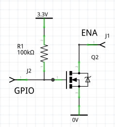
An alternative, slightly less efficient approach, is to pull down ENA with
a 2.2KΩ resistor and link it to a GPIO pin. The breakout has a 100KΩ resistor
to Vin. The 2.2KΩ resistor causes the breakout and display to assume the power
off state if the GPIO pin is high impedance.
The test script epd29_lowpower.py assumes pin Y5 linked to the breakout
enable. I used the 2.2KΩ resistor pull down. The code comments clarify the mode
of operation. The demo wakes every 30s. Real applications would do it much less
frequently with attendant power savings.
Users of other EPD's may want to develop other means of powering down the EPD. A p-channel MOSFET could be considered as described here.
Measurements
In use I measured 58μA between wakeups. The Pyboard accounts for about 6μA. 33μA will be used by the 100KΩ pullup on the breakout's power enable line. I haven't attempted to figure out where the other 19μA is going.
I measured power consumption for a hypothetical application which wakes once per hour, refreshes the screen, and goes back to sleep. In summary it uses 0.74AH per year. This suggests it could run for ~3 years on a set of alkaline AA cells (capacity 2.5AH).
Of the total, the 58μA sleep current accounts for 0.5AH, and the wakeup current 0.24AH. Of the wakeup current, 28% is used for physical display refresh and a further 39% during SPI transfer to the display. The remaining 33% is used by boot (3%), initialisation of the device (2.8%), and initialisation of nano-gui (27%). This is based on study of the current waveform in conjunction with guessing what is going on in each phase of operation.
The measurements used frozen bytecode on a Pyboard D SF6W. No SD card was
fitted. Code was epd29_lowpower.py with the red LED code removed.
The fact that nearly 70% of the energy is used in standby suggests improvements. If the EPD subsystem were turned off by a p-channel MOSFET, current consumption could be reduced to the 6μA figure of the Pyboard, an order of magnitude improvement.
Contents
5.2 Waveshare eInk Display HAT
This 2.7" 176*274 display is designed for the Raspberry Pi and is detailed here.
I bought two of these units from different sources. Both have hardware issues discussed here. I have failed to achieve consistent behaviour. Units behave perfectly one day and fail the next. I published this driver on the assumption that I was twice sold dubious Chinese clones and that genuine ones would be reliable.
The driver is cross-platform.
Wiring
This shows the Raspberry Pi connector looking at the underside of the board
with the bulk of the board to the right. Only the top portion of the 40-way
connector is shown, with connections to a Pyboard to match waveshare_setup.py.
Connections may be adapted for other MicroPython targets. The board may be powered from 5V or 3.3V: there is a regulator on board.
| Pyb | L | R | Pyb | ||
|---|---|---|---|---|---|
| Vin | VIN | 2 | 1 | ||
| 4 | 3 | ||||
| 6 | 5 | ||||
| 8 | 7 | ||||
| 10 | 9 | GND | Gnd | ||
| 12 | 11 | RST | Y3 | ||
| 14 | 13 | ||||
| 16 | 15 | ||||
| Y4 | BUSY | 18 | 17 | ||
| 20 | 19 | MOSI | Y8 | ||
| Y1 | DC | 22 | 21 | ||
| Y2 | CS | 24 | 23 | SCLK | Y6 |
Pins 26-40 unused and omitted.
5.2.1 EPD constructor args
spiAn initialised SPI bus instance. The device can support clock rates of upto 2MHz.csAn initialised output pin. Initial value should be 1.dcAn initialised output pin. Initial value should be 0.rstAn initialised output pin. Initial value should be 1.busyAn initialised input pin.landscape=FalseBy default the long axis is vertical.
The asyn arg has been removed: the driver now detects asynchronous use.
5.2.2 EPD public methods
All methods are synchronous.
initNo args. Issues a hardware reset and initialises the hardware. This is called by the constructor. It needs to explicitly be called to exit from a deep sleep.sleepNo args. Puts the display into deep sleep. If called while a refresh is in progress it will block until the refresh is complete.sleepshould be called before a power down to avoid leaving the display in an abnormal state.readyNo args. After issuing arefreshthe device will become busy for a period:readystatus should be checked before issuingrefresh.wait_until_readyNo args. Pause until the device is ready.
5.2.3 Events
These provide synchronisation in asynchronous applications. They are only needed in more advanced asynchronous applications and their use is discussed in EPD Asynchronous support.
updatedSet when framebuf has been copied to device. It is now safe to modify widgets without risk of display corruption.completeSet when display update is complete. It is now safe to callssd.refresh().
5.2.4 Public bound variables
heightInteger. Height in pixels. Treat as read-only.widthInteger. Width in pixels. Treat as read-only.demo_mode=FalseBoolean. If setTrueafter instantiating,refresh()will block until display update is complete, and then for a further two seconds to enable viewing. This enables generic nanogui demos to be run on an EPD.
Note that in synchronous applications with demo_mode=False, refresh returns
while the display is updating. Applications should issue wait_until_ready
before issuing another refresh.
5.3 Waveshare 400x300 Pi Pico display
There are two drivers for this display:
pico_epaper_42.py1-bit black/white driver supports partial updates.pico_epaper_42_gs.py2-bit greyscale driver. No partial updates.
The drivers have identical args and methods.
This 4.2" display supports a Pi Pico or Pico W plugged into the rear of the
unit. Alternatively it can be connected to any other host using the supplied
cable. With a Pico variant the color_setup file is very simple:
import machine
import gc
from drivers.epaper.pico_epaper_42 import EPD as SSD

gc.collect()  # Precaution before instantiating framebuf.
ssd = SSD()  # Create a display instance based on a Pico in socket.
5.3.1 Constructor args
For other hosts the pins need to be specified in color_setup.py via the
following constructor args:
spi=NoneAn SPI bus instance defined with default args.cs=NoneAPininstance defined asPin.OUT.dc=NoneAPininstance defined asPin.OUT.rst=NoneAPininstance defined asPin.OUT.busy=NoneAPininstance defined asPin.IN, Pin.PULL_UP.
The asyn arg has been removed: the driver now detects asynchronous use.
5.3.2 Public methods
All methods are synchronous.
initNo args. Issues a hardware reset and initialises the hardware. This is called by the constructor. It needs to explicitly be called to exit from a deep sleep.sleepNo args. Puts the display into deep sleep. If called while a refresh is in progress it will block until the refresh is complete.sleepshould be called before a power down to avoid leaving the display in an abnormal state.readyNo args. After issuing arefreshthe device will become busy for a period:readystatus should be checked before issuingrefresh.wait_until_readyNo args. Pause until the device is ready.set_partial()Enable partial updates (does nothing on greyscale driver).set_full()Restore normal update operation (null on greyscale driver).
On the 1-bit driver, after issuing set_partial(), subsequent updates will be
partial. Normal updates are restored by issuing set_full(). These methods
should not be issued while an update is in progress.
Partial updates are fast and visually unobtrusive but they are prone to ghosting.
5.3.3 Events
These provide synchronisation in asynchronous applications. They are only needed in more advanced asynchronous applications and their use is discussed in EPD Asynchronous support.
updatedSet when framebuf has been copied to device. It is now safe to modify widgets without risk of display corruption.completeSet when display update is complete. It is now safe to callssd.refresh().
5.3.4 Public bound variables
heightInteger. Height in pixels. Treat as read-only.widthInteger. Width in pixels. Treat as read-only.demo_mode=FalseBoolean. If setTrueafter instantiating,refresh()will block until display update is complete, and then for a further two seconds to enable viewing. This enables generic nanogui demos to be run on an EPD.
Note that in synchronous applications with demo_mode=False, refresh returns
while the display is updating. Applications should issue wait_until_ready
before issuing another refresh.
5.3.5 The greyscale driver
This is unsuitable for micro-gui because of its lack of partial updates.
The greyscale driver will render code written for color screens, but the mapping of colors onto the limited number of grey values is unlikely to be ideal. It's best to choose colors specifically for this display. The following illustrates its use:
from color_setup import ssd  # Create a display instance
from gui.core.nanogui import refresh
refresh(ssd, True)  # Initialise and clear display.
ssd.wait_until_ready()
ssd.fill(0)
ssd.line(0, 0, ssd.width - 1, ssd.height - 1, 3)  # Black diagonal corner-to-corner
ssd.rect(0, 0, 15, 15, 2)  # Dark grey square at top left
ssd.rect(ssd.width -15, ssd.height -15, 15, 15, 1)  # Light grey square at bottom right
ssd.fill_rect(0, 50, 15, 15, 1)  # Light grey
ssd.fill_rect(0, 70, 15, 15, 2)  # Dark grey
ssd.fill_rect(0, 90, 15, 15, 3)  # Black
refresh(ssd)
Color values of 0 (white) to 3 (black) can explicitly be specified.
Contents
5.4 WeAct Studio SSD1680 eInk Displays
The driver supports the WeAct Studio SSD1680 2.9 inch 296*128 pixel display that uses the SSD1680 driver.
This display lacks many features when compared to the ones from Waveshare, two important examples are fast refresh and partial refresh. The big pro however is the price, it costs half the money of the Waveshare 2.9in alternative.
The driver is cross platform and supports landscape or portrait mode. To keep the buffer size down (to 4736 bytes) there is no greyscale support. It should be noted that WeAct Studio product page suggests to not update the display more frequently than every 180s.
6. EPD Asynchronous support
The following applies to nano-gui. Under micro-gui the update mechanism is a background task. Use with micro-gui is covered here.
When synchronous code issues
refresh(ssd) # Several seconds on an EPD
the GUI updates the frame buffer contents and calls the device driver's show
method. This causes the contents to be copied to the display hardware and a
redraw to be inititated. This typically takes several seconds unless partial
updates are enabled. The method (and hence refresh) blocks until the physical
refresh is complete. If demo_mode is set, device drivers block for an
additional 2 seconds to enable demos written for normal displays to work (the
2 second pause allows the result of each refresh to be seen).
This long blocking period is not ideal in asynchronous code. If refresh is
called from a task, refresh calls the show method as before, but show
creates a task ._as_show and returns immediately. The task yields to the
scheduler as necessary to ensure that blocking is limited to around 30ms. If
screen updates take place at a low rate the only precaution necessary is to
ensure that sufficient time elapses between calls to ssd.refresh() for the
update to complete. For example the following code fragment illustrates an
application which performs a full EPD refresh once per minute:
async def run():
    while True:
        # get data
        # Update screen widgets
        ssd.refresh()  # Launches background refresh
        await asyncio.sleep(60)
Other running tasks experience latency measured in tens of ms.
Finer control is available using the two public bound Event instances. This
fragment assumes an application with a single task performing refreshes. The
application has two Event instances, one requesting refresh and the other
requesting widget updates:
async def refresh_task():
    while True:
        await refresh_request.wait()  # Another task has requested refresh
        refresh_request.clear()
        ssd.refresh()  # Launch background refresh
        await ssd.updated.wait()  # Wait until framebuf copied to device
        data_request.set()  # Ask other tasks to update widgets
        await ssd.complete.wait()
        # Now safe to respond to refresh_request and issue ssd.refresh()
The updated and complete events are cleared when ssd.refresh is called
and are set as the background refresh proceeds.
Some displays support partial updates. This is currently restricted to the Pico Epaper 4.2". Partial updates are much faster and are visually non-intrusive at a cost of "ghosting" where black pixels fail to be fully cleared. All ghosting is removed when a full refresh is issued. Where a driver supports partial updates the following synchronous methods are provided:
set_partial()Enable partial updates.set_full()Restore normal update operation. These must not be issued while an update is in progress.
See the demo eclock_async.py for an example of managing partial updates: once
per hour (on the half-hour) a full update is performed.
Contents
7. Writing device drivers
Device drivers capable of supporting nanogui can be extremely simple: see
drivers/sharp/sharp.py for a minimal example. It should be noted that the
supplied device drivers are designed purely to support nanogui. To conserve RAM
they provide no functionality beyond the transfer of an external frame buffer
to the device. This transfer typically takes a few tens of milliseconds. While
visually instant, this period constitutes latency between an event occurring
and a consequent display update. This may be unacceptable in applications such
as games. In such cases the FrameBuffer approach is inappropriate. Many
driver chips support graphics primitives in hardware; drivers using these
capabilities will be faster than those provided here and may often be found
using a forum search.
7.1 The basics
For a driver to support nanogui it must be subclassed from
framebuf.FrameBuffer and provide height and width bound variables being
the display size in pixels. This, and a show method, are all that is required
for monochrome drivers. If a monochrome display driver must be "color
compatible" - i.e. to run code written for color displays (such as the demo
scripts) please read on.
7.2 Color and color compatible drivers
These include color drivers, monochrome drivers that must run color code and greyscale drivers where a color value maps onto a monochrome pixel brightness.
Some additional boilerplate code is required for such drivers to enable them to render monochrome object such as glyphs. To enable a monochrome driver to run code written for color displays it too should incorporate this code. Otherise the script will fail with an "Incompatible device driver" exception.
from drivers.boolpalette import BoolPalette
# In the constructor:
        mode = framebuf.GS8  # Whatever mode the driver uses
        self.palette = BoolPalette(mode)
        super().__init__(buf, self.width, self.height, mode)
The GUI achieves hardware independence by using 24 bit color (RGB888). The
driver must convert this to a format used by the hardware. In normal drivers
the FrameBuffer stores values in a form compatible with the hardware.
Conversion from RGB888 to the format in the FrameBuffer is done by a static
rgb method. In the case of a monochrome display, any color with high
brightness is mapped to white with:
    @staticmethod
    def rgb(r, g, b):
        return int(((r | g | b) & 0x80) > 0)
A typical color display with 8-bit rrrgggbb hardware will use:
    @staticmethod
    def rgb(r, g, b):
        return (r & 0xe0) | ((g >> 3) & 0x1c) | (b >> 6)
A greyscale display typically maps RGB values onto a 4-bit greyscale color space:
    @staticmethod
    def rgb(r, g, b):
        return (r + g + b) // 48  # Mean bightness scaled to fit 4 bits
The above, plus a show method, describes a driver where the values stored in
the frame buffer match the color values expected by the hardware. This is
normally preferred on grounds of simplicity. However it can lead to a need for
a large buffer if the hardware requires 16 bit pixels and/or the display has a
large number of pixels. In such cases the display driver can use a smaller
pixel size using modes designed for 8 or 4 bit greyscales to store colors, with
expansion occurring at runtime. Such drivers are described as mapped drivers.
7.3 Show
Refresh must be handled by a show method taking no arguments; when called,
the contents of the buffer underlying the FrameBuffer must be output to the
hardware.
7.4 Mapped drivers
In the simplest case the FrameBuffer mode is chosen to match a mode used by
the hardware. The rgb static method converts colors to that format and
.show writes it out.
In some cases this can result in a need for a large FrameBuffer, either
because the hardware can only accept 16 bit color values or because the
display has a large number of pixels. In these cases the FrameBuffer uses
a mode for 8 bit or 4 bit color with mapping taking place on the fly in the
.show method. To maximise update speed consider using native, viper or
assembler for this mapping.
7.4.1 8 to 16 bit mapping
An example of hardware that does not support 8 bit color is the SSD1351. See
this driver1.
This uses framebuf.GS8 to store 8 bit color in rrrgggbb format. The .show
method converts these to 16-bit values at run time.
In this case the FrameBuffer uses framebuf.GS8 to store colors in RGB332
format. The rgb static method converts 24 bit r, g, b colors to RGB332. The
.show method converts from RGB332 to RGB565 and outputs the data.
7.4.2 4 to N bit mapping
The minimum RAM use arises if the FrameBuffer stores 4-bit values which are
indices into a color lookup table (LUT). The LUT holds a set of upto 16 colors
stored in the display's native format. Such a driver configures the
FrameBuffer in GS4_HMSB mode. The class must include the class variable
lut - this example is for a 16-bit color display:
class MY_DRIVER(framebuf.FrameBuffer):
    lut = bytearray(32)  # Holds 16x16-bit color values
This is a lookup table (LUT) mapping a 4-bit index onto an N-bit color value
acceptable to the hardware. The "on the fly" converter unpacks the values in
the frame buffer and uses them as indices into the lut bytearray. See the
various 4-bit drivers such as
ILI9341.
In this case the rgb static method converts 24 bit r, g, b colors to the
format expected by the hardware. It is used to populate the LUT. There is an
endian-ness issue here if the colors required by the hardware are bigger than 8
bits. The convention I use is that the LS byte from .rgb() is transmitted
first. So long as .rgb() and the "on the fly" converter match, this choice is
arbitrary.
7.5 Debugging
If the above guidelines are followed the Writer (monochrome) or CWriter
(color) classes, nanogui and micro-guimodules should then work
automatically.
The following script is useful for testing color display drivers after
configuring color_setup.py. It draws squares at the extreme corners of the
display and a corner to corner diagonal. The nature of this image makes
faultfinding much simpler than viewing a garbled GUI screen.
from color_setup import ssd  # Create a display instance
from gui.core.colors import RED, BLUE, GREEN
from gui.core.nanogui import refresh
refresh(ssd, True)  # Initialise and clear display.
# Uncomment for ePaper displays
# ssd.wait_until_ready()
ssd.fill(0)
ssd.line(0, 0, ssd.width - 1, ssd.height - 1, GREEN)  # Green diagonal corner-to-corner
ssd.rect(0, 0, 15, 15, RED)  # Red square at top left
ssd.rect(ssd.width -15, ssd.height -15, 15, 15, BLUE)  # Blue square at bottom right
ssd.show()
If this produces correct output the GUI's can be expected to work.
Authors of device drivers are encouraged to raise an issue or PR so that the library can be extended.
7.6 Reducing blocking time in show
This is available for micro-gui only. The blocking time of the .show method
is reduced by splitting it into segments and yielding to the scheduler after
each segment. It is handled transparently by the GUI. It consists of providing
an asynchronous do_refresh method taking an integer split arg. See
the ili9341 driver
for an example. The GUI will pass a split value which is a divisor of the
number of lines in the display. The do_refresh method calculates the number
of lines in each segment. For each segment it outputs those lines and yields
to the scheduler.
7.7 ePaper drivers
These are not supported by micro-gui owing to their very slow refresh time.
They are supported by Witer, CWriter and nano-gui.
Owing to the long refresh periods some synchronisation is necessary. This
comprises ready and wait_until_ready methods. The ready method
immediately returns a bool indicating if the hardware can accept data. The
wait_until_ready method blocks until the device is ready to accept data. This
is all that is required for synchronous applications. The .show. method calls
wait_until_ready at the end, removing the need for explicit synchronisation
in the application. The cost is that display refresh blocks for a long period.
For applications using asynchronous code this blocking is usually unacceptable.
It can be restricted to a single task, with others, able to continue running by
adding two asynchronous methods, .wait and .updated. The .wait method is
an asynchronous version of .wait_until_ready. The .updated method is issued
after a refresh has been issued and pauses until the physical refresh is
complete. After a refresh applications should avoid changing the frame buffer
contents until .updated has returned. They should wait on .wait before
issuing .refresh.