|
|
||
|---|---|---|
| images | ||
| .gitignore | ||
| LICENSE | ||
| README.md | ||
| ax25_callsign.cpp | ||
| ax25_callsign.h | ||
| ax25_payload.cpp | ||
| ax25_payload.h | ||
| ble_serial.cpp | ||
| ble_serial.h | ||
| config.h | ||
| esp32_loraprs.ino | ||
| kiss_processor.cpp | ||
| kiss_processor.h | ||
| loraprs_config.h | ||
| loraprs_service.cpp | ||
| loraprs_service.h | ||
README.md
Table of contents
- Introduction
- Compatible Boards
- Software Dependencies
- Software Setup
- BLE Usage iOS
- Protocol Compatibility
- Alternative Linux Setup
- CSMA Usage
- Digital voice with Codec2
- KISS command extensions
- Using External UHF Amplifier
- Test Results
- TODO
Introduction
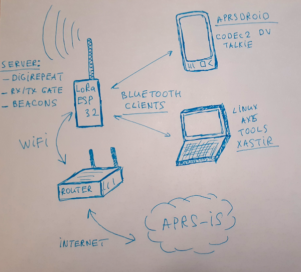
Amateur radio ESP32 based LoRa APRSDroid KISS Bluetooth modem + LoRa APRS-IS RX/TX iGate server over WiFI + digipeater + Codec2 DV modem (in conjunction with Android frontend application)
Can be used in two modes, mode seleciton is done by changing cfg.IsClientMode or CFG_IS_CLIENT_MODE define in config.h:
- LoRa APRS KISS client over bluetooth, WiFi and iGate are switched off, mobile or portable usage (/M, /P)
- you need to use APRSDroid application (https://aprsdroid.org) or iOS aprs.fi official application, connect to the modem using bluetooth, data will be re-transmitted through the LoRa radio, this is similar to APRSDroid micromodem - https://unsigned.io/micromodem/, received data will be sent back to the APRSDroid using bluetooth
- by having two APRSDroid clients you can not only send your position, but also send and receive APRS messages
- it is also possible to use other KISS APRS clients over Bluetooth serial, just use
rfcommon Linux to setup serial over Bluetooth and put up AX25 interface withkissattach, then use any existing Linux APRS clients, such asxastir, see section below for alternative Linux usage
- LoRa APRS iGate RX/TX server over WiFi + Digipeater, stationary usage at home
- RF to APRS-IS gating, it will connect to your WiFI and will forward received APRS positions from RF LoRa into the APRS-IS network, it also reports client signal level, by appending it into the APRS comment, so you can see your signal reports in different locations (could be enabled or disabled from config). This way, it is also possible to setup portable iGate by connecting to your mobile phone's hotspot and provide power from the phone USB port by using USB-OTG cable
- APRS-IS to RF gating, it is possible to enable it together with the filter in the config, so APRS-IS data will be forwarded to RF
- RF digirepating for
WIDEn-nnew style paths - Beaconing, own station periodic beacon announcement to APRS-IS and RF
- if
cfg.BtNameis NOT set to empty string then server mode also allows to connect with KISS bluetooth client and use it simulatenously with iGate functionality, e.g. when stationary at home and want to use DV Codec2 Walkie-Talkie voice communication
Modem could also be used for LoRa Codec2 digital voice DV communication
- just install Codec2 Walkie-Talkie on you Android phone, pair with the modem and you can communicate with each other by using digital voice Codec2, also modem can be controlled from this application (frequency change, bandwidth, spreading factor, etc)
Compatible Boards
All work was done on ESP32-WROOM with custom made LoRa shield, Arduino Board is "ESP32 Dev Module".
Supported modules - modules, which are supported by RadioLib.
If your ESP32 board is compatible or has built in LoRa module then it should work without redefining pinouts, for custom shields there might be need to redefine pinouts to LoRa module if it differs (see further description in Software Setup section), currently pinouts are connected from LoRa to ESP32-WROOM as (SS/RST/DIO0 could be redefined in config.h):

Pinouts:
- Common SPI:
- MOSI: GPIO_23/VSPI_MOSI
- MISO: GPIO_19/VSPI_MISO
- SCK: GPIO_18/VSPI_SCK
- Board specific:
- SS/CS/NSS: GPIO_5
- RST/RESET: GPIO_26
- DIO0/IRQ: GPIO_14
![]()
Supported (built-in screen is not used), just select board in Arduino IDE->Tools->Board, no need to redefine pinouts:
- T-Beam LoRa
- LoPy, LoPy4
- TTGO LoRa32 v1
Require LoRa module pinout definitions in config.h:
- Heltec WiFi LoRa 32 (v2), redefine pinouts as
#define LORA_RST              14
#define LORA_IRQ              26
Software Dependencies
Install via libraries:
- Arduino ESP32 library: https://github.com/espressif/arduino-esp32
- LoRa arduino library: https://github.com/sandeepmistry/arduino-LoRa
- or RadioLib library (use github master version): https://github.com/jgromes/RadioLib
- Arduino Timer library: https://github.com/contrem/arduino-timer
- CircularBuffer library: https://github.com/rlogiacco/CircularBuffer
Software Setup
- Decide if you want to use arduino-LoRa or RadioLib library, you have to use RadioLib library if you are NOT using
SX127xmodule, uncommentUSE_RADIOLIBin sketch if you want to use RadioLib- If you are using RadioLib and not using SX1278 module then modify module declarations in
loraprs_service.cppandloraprs_service.hfind and replaceSX1278with your module name. Read more about supported modules at RadioLib Wiki.
- If you are using RadioLib and not using SX1278 module then modify module declarations in
- NB! select next partition scheme for ESP32 in Arduino IDE Tools menu: "Minimal SPIFFS (1.9 MB APP with OTA/190 KB SPIFFS)"
- for boards, which do not have this option, need to modify
~/.arduino15/packages/esp32/hardware/esp32/1.0.4/boards.txtand add required partition option
- for boards, which do not have this option, need to modify
- use 80 MHz ESP32 frequency in Arduino SDK, it will prolong battery life when operating portable, higher CPU speed is not required, there are no CPU intensive operations
- when setting up APRSDroid, use "TNC (KISS)" connection protocol in Connection Preferences -> Connection Protocol
- go to esp32_loraprs.ino and make next changes based on your requirements in
initializeConfig()- set
cfg.IsClientModetofalseif you are planning to run server mode for APRS-IS iGate / Digipeater - for server mode fill
cfg.WifiSsidandcfg.WifiKeywith your WiFI AP data - for server mode fill
cfg.AprsLoginandcfg.AprsPasswith APRS-IS login callsign and pass - for server mode fill
cfg.AprsFilter, see http://www.aprs-is.net/javAPRSFilter.aspx for various formats, do not includefilterdirective, just space separated values - change
cfg.LoraFreqif you are planning to use different frequency or if planning to calibrate clients, currently it is set to 433.775MHz as per https://vienna.iaru-r1.org/wp-content/uploads/2019/01/VIE19-C5-015-OEVSV-LORA-APRS-433-MHz.pdf
- set
- if you are planning to use different esp32 pinouts then modify config.h
- lora module SS, CFG_LORA_PIN_SS, GPIO_5
- lora module RST, CFG_LORA_PIN_RST, GPIO_26
- lora module DIO0, CFG_LORA_PIN_DIO0, GPIO_14
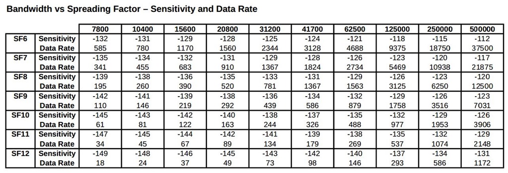
- if you are planning to experiment with different bandwidths/spread factors then modify values in
initializeConfig(), with current parameters APRS packet time on air is around 1-2 seconds @ 292bps/36Bps, to decode with as lower level as possible with reasonable speed (comparable to 300bps HF APRS), use https://github.com/tanupoo/lorawan_toa or https://www.rfwireless-world.com/calculators/LoRa-Data-Rate-Calculator.html to make further calculations- lora bandwidth
cfg.LoraBw, 125 kHz (also tested with 20.6 KHz and SF9 with frequency correction) - lora spread factor
cfg.LoraSf, 12 (should decode down to -20dB, choosen with the goal for minimum signal decode) - lora coding rate
cfg.LoraCodingRate, 7 - lora output power
cfg.LoraPower, 20 (max 20 dBm ~ 100mW, change to lower value if needed) - sync word
cfg.LoraSync, 0x34
- lora bandwidth
- consider minimum decode level based on on BW + SF and required throughput
- uses LoRa built-in checksum calculation to drop broken packets
- note, that there a is significant frequency drift on temperature changes for different modules
- you need to use external TCXO if you are planning to use modules for narrow bandwidths less than 125 kHz
- or calibrate clients based on server frequency drift report by changing
cfg.LoraFreq, for example, let client and server run for an 30-60 minutes and if server reports err: -1500, then set client frequency to about 1000 kHz less, e.g. instead of 433.775 set it to 433.774, this will give couple of additional dB - alternatively automatic calibration could be done on server or client side by enabling automatic frequency correction by setting
cfg.EnableAutoFreqCorrectiontotrue, might be suitable for experiments where only one client is operating or if server broadcast messages, so clients can correct their frequency. Use it either on client side to tune all clients to server frequency if TX is enabled on iGate side or to tune server to single client for test purposes
- other useful options are
cfg.EnableSignalReportset totrueto enable signal report, it will be added as a comment to APRS-IS submitted locationcfg.EnablePersistentAprsConnectionset tofalseto avoid keeping connection open to APRS-IScfg.EnableRfToIsset totrueto forward RF traffic to APRS-IScfg.EnableIsToRfset totrueto forward APRS-IS traffic to RF, see alsocfg.AprsFilterfor traffic filteringcfg.EnableRepeaterset totrueto enable packet repeatercfg.EnableBeaconset totrueto enable periodic beacons specified incfg.AprsRawBeaconwith period specified incfg.AprsRawBeaconPeriodMinutesinto RF and APRS-IS ifcfg.EnableRfToIsis enabledcfg.LoraUseIsrset totrueto enable LoRa incoming packet handling using interrupts in continous RX mode suitable for speech data, otherwise set tofalsefor single packet polling mode
BLE Usage iOS
- iOS does not support serial over Bluetooth and requires BLE support, this enables APRS applications such as official aprs.fi to work with the modem
- to enable BLE support set
cfg.BtEnableBletotrue
Protocol Compatibility
- Make sure LoRa sync word and other LoRa parameters match
- Client should be interoperable with other clients, which transmit raw text APRS messages if bluetooth client sends them in this format to the modem
- Server supports only classical
AX25frames over LoRa (as defined in http://www.aprs.org/doc/APRS101.PDF page 12). It should enable interoperability with classical Linux APRS software, such as Xastir withkissattach. Some LoRa ARPS implementations transfer plain text APRS messages over LoRa, as a result Server will not be able to process these messages and gate them to APRS-IS, also clients won't be able to decode messages gated from APRS-IS to RF by the server
Alternative Linux Setup
It is possible to use modem in client mode with other generic Linux AX25/APRS tools on PC or Raspberry, such as Xastir, use next procedure to set it up:
- AX25 howto: http://tldp.org/HOWTO/AX25-HOWTO/
- Install required tools:
sudo apt-get install ax25-tools ax25-apps xastir bluez bluez-tools - Run bluetoothctl and pair with the modem:
# bluetoothctl [bluetooth]# agent on [bluetooth]# default-agent [NEW] Device 01:02:03:04:05:06 loraprs [bluetooth]# pair 01:02:03:04:05:06 Attempting to pair with 01:02:03:04:05:06 Pairing successful [bluetooth]# exit - Run
rfcommto setup serial over Bluetooth at/dev/rfcomm0:sudo rfcomm bind 0 01:02:03:04:05:06 - At this stage you can already start using
xastiror any other application, which can operate over KISS Serial TNC - You can setup
AX25network interface withsudo kissattach /dev/rfcomm0 ax25command, but previously need to update/etc/ax25/axportswith new line asax25 CALLSIGN-10 9600 255 1 comment, you can also specify IP address if there is a need to run TCP/IP over AX25 - Run
axlistento capture incoming and outgoing traffic assudo axlisten -a - Use
beaconutility to send custom packet as# sudo beacon -s -c NOCALL-7 -d "BEACON WIDE3-3" ax25 "beacon over lora" # sudo beacon -s -c NOCALL-7 -d "CQ WIDE1-1 WIDE2-1" ax25 "anyone on lora?" # sudo beacon -s -c NOCALL-7 -d "APZMDM WIDE1-1" ax25 "!0000.00N/00000.00E#test position report" - Connect to another client as
sudo axcall -s NOCALL-1 ax25 NOCALL-10
CSMA Usage
- LoRa library, which is in use by this project does not implement CAD, but CSMAp is utilized by this project as per KISS specification. TX path is executed only when there is no incoming data returned by
LoRa::parsePacketand TX path is executed with probability p (CSMA persistence), configured by constLoraprs::Service::CfgCsmaPersistenceinloraprs_service.h. Random value is selected between 0 and 255 and TX is executed only when it is lower thanCfgCsmaProbBoundary. - To decrease TX probability in case of high traffic use lower value.
Loraprs::ServiceCsmaSlotTimeMsconfigures the amount of time in milliseconds to wait if transmission was not performed due to persistence, select lower value for lower TOA (time on air). It is also possible to dynamically override these parameters with KISS P 0x02 and SlotTime 0x03 command codes from the client.
Digital voice with Codec2
- This modem could be used in conjuction with Android Codec2 Walkie-Talkie, when application connects to the modem, instead of sending AX25 APRS packets it sends Codec2 speech encoded frames. This enables digital voice communicaiton between one or multiple modems.
- Select appropriate lora spread factor
cfg.LoraSfand bandwidthcfg.LoraBwdepending on Codec2 speech rate from 450-3200 bps. For example, if you are using 450 bps mode and 20 kHz bandwidth then set spreading factor to 6 or 7. See data rate table above. - When using modem for voice communication
Loraprs::Service::CfgCsmaPersistencemust be set to maximum 255 value to disable CSMA, otherwise real time voice communication won't be guaranteed. Android codec2_talkie application automatically sets this parameter to 255 by using KISS P command code. - Also, it might be useful to disable CRC check for LoRa packets with
cfg.LoraEnableCrcparameter equal tofalse. Some broken bits in one speech frame will cause audio being scrambled, it might be better then longer gap when complete packet is dropped.
KISS command extensions
When EnableKissExtensions configuration parameter is set to true modem will be able to handle SetHardware KISS command 6 for setting modem parameters and will send event about signal level with KISS command 7, both are operating on KISS port 0. This way client application (such as Codec2 Walkie-Talkie) can display signal levels and change modem parameters dynamically.
Payloads for commands are sent and expected as big endian and defined as:
  // KISS SetHardware 6
  struct SetHardware {
    uint32_t freq;
    uint32_t bw;
    uint16_t sf;
    uint16_t cr;
    uint16_t pwr;
    uint16_t sync;
    uint8_t crc;
  } __attribute__((packed));

  // KISS command 7
  struct SignalReport {
    int16_t rssi;
    int16_t snr;  // snr * 100
  } __attribute__((packed));

  // KISS command 8
  struct RebootModem {
  } __attribute__((packed));
Using External UHF Amplifier

It is possible to get 30-40% TX only coverage increase in urban environment by using additional external 1-2W amplifier (about 6$ on Aliexpress), which will give 10-12 dB signal increase, achieved approximately 20 km coverage in moderate urban environment and about 15 km with almost 100% packet receiving.
- Implement simple amplifier power switching by using relay, do NOT keep this amplifier always ON
- Set LoRa output power to around 8 dBm
cfg.LoraPwr = 8;, NB! higher than 10 dBm levels can destroy amplifier - Set
cfg.PttEnabletotrue - Set
cfg.PttPinto your relay control pin - Optionally change
cfg.PttTxDelayMsandcfg.PttTxTailMsdepending on your relay switching times
Test Results
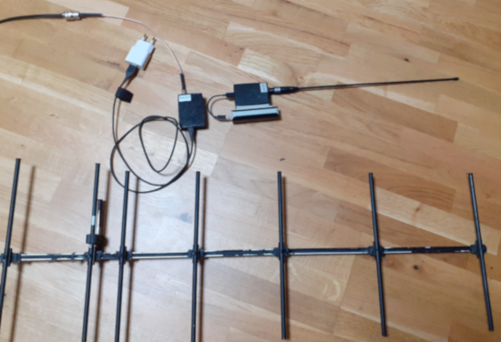
- Antennas
- Client: rubber duck, halo, mobile antenna on a car roof
- Server: 7 element UHF yagi indoors, vertical on the roof
- With such low power it is very important to have antenna SWR close to 1, many rubber duck antennas are claimed to be 433MHz, but they do not resonate at that frequency at all or resonate only when attached to its native large handheld transceiver, which has enough metal inside to behave as a counterpoise, these antennas have SWR 2 or higher. Check your antenna on antenna analyzer before using, add wire counterpoise if needed or better to use dipole or halo home made antenna for that matter
- Range (20 KHz channel width and 9 spreading factor, also got similar results with 125 kHz and 12 SF), it will mostly depend on your base station's antenna elevation
- About 7 km when server is 30m above the ground and client is 2m above the ground with rubber duck antenna or inside a car
- About 13 km when server is 30m above the ground and client is at some higher point ~40m above the ground with rubber duck antenna
- About 17km maximum (non-reliable) between base and mobile station with antenna on the car roof
- About 20km over the sea between base and handheld
- Signal levels
- Successful decodes down to -19.75dB below the noise floor when using compressed APRS coordinates (smaller packets, about 50 bytes, 32 bytes without PATH, speed, altitude), see APRSDroid discussions on compressed corrdinates support and custom branches
- Polarization
- Using horizontal polarization improves successful decoding probability and receiving range
- Interference
- Monitor your planned frequency, such as 433.775 MHz for ISM device activity, if there is strong interference from other users tune up or down it to minimize interference, it might be critical for long range
- Weather
- Rain and high humidity levels decrease signal level by about ~3-6 dB on 433 MHz, could be higher on 868 MHz
- It might be useful to add additional pass band filter or broadcast FM radio reject filter, it seem to improve sensitivity when using external base antenna
TODO
- Improve CSMA logic and if possible add support for CAD
- Investigate support for M17 Protocol reflector gating in addition to APRS-IS when M17 protocol is used by the client application