kopia lustrzana https://github.com/sh123/esp32_loraprs
amateur-radioaprsaprs-rxaprs-trackeraprsdroidaprsiscodec2esp32esp32-ardunioesp32-libraryham-radioiotkissloralora-gatewaylora-serverlorawantnctrackeruhf
|
|
||
|---|---|---|
| .gitignore | ||
| README.md | ||
| esp32_loraprs.ino | ||
| loraprs.cpp | ||
| loraprs.h | ||
README.md
Experimental LoRa APRS ESP32 APRSDroid bluetooth modem and LoRa APRS-IS iGate
Tiny experimental amateur radio ESP32 based LoRa APRSDroid KISS Bluetooth modem and LoRa APRS-IS iGate server.
Can be used in two modes:
- as a LoRa APRS client, you need to use APRSDroid application (https://aprsdroid.org), connect to the modem using bluetooth, data will be re-transmitted through the LoRa radio, this is similar to APRSDroid micromodem - https://unsigned.io/micromodem/, received data will be sent back to the APRSDroid using bluetooth. By having two clients you can not only send your position, but also send and receive APRS messages.
- as a LoRa APRS iGate server, which connects to your WiFI and forwards received LoRa APRS positions into the APRS-IS network, it also reports client signal level, by appending it into the APRS comment, so you can see your signal reports in different locations
Software Dependencies (install via libraries)
- Arduino ESP32 library: https://github.com/espressif/arduino-esp32
- LoRa arduino library: https://github.com/sandeepmistry/arduino-LoRa
- Arduino Timer library: https://github.com/contrem/arduino-timer
Software Setup
- when setting up APRSDroid, use "TNC (KISS)" connection protocol in Connection Preferences -> Connection Protocol
- go to esp32_loraprs.ino and make next changes based on your requirements
- comment out / remove LORAPRS_CLIENT define if you are planning to run server mode for APRS-IS iGate
- for server mode fill LORAPRS_WIFI_SSID and LORAPRS_WIFI_KEY with your WiFI AP data
- for server mode fill LORAPRS_LOGIN and LORAPRS_PASS with APRS-IS login callsign and pass
- change LORAPRS_FREQ if you are planning to use different frequency or if planning to calibrate clients, currently it is set to 433.775MHz as per https://vienna.iaru-r1.org/wp-content/uploads/2019/01/VIE19-C5-015-OEVSV-LORA-APRS-433-MHz.pdf
- if you are planning to use different esp32 pinouts then modify loraprs.h
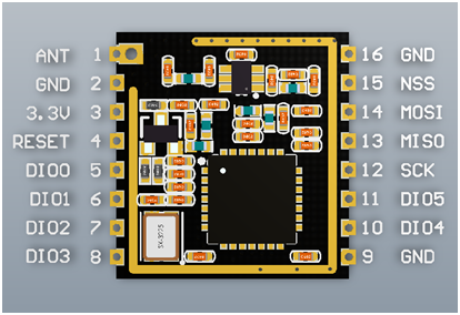
- lora module SS, CfgPinSs, pin 5
- lora module RST, CfgPinRst, pin 26
- lora module DIO0, CfgPinDio0, pin 14
- if you are planning to experiment with different bandwidths/spread factors then modify loraprs.h, with current parameters APRS packet time on air is around 2 seconds to decode with as lower level as possible, use https://github.com/tanupoo/lorawan_toa to make calculations
- lora bandwidth CfgBw, 125 kHz
- lora spread factor CfgSpread, 12 (should decode down to -20dB, choosen with the goal for minimum signal decode)
- lora coding rate CfgCodingRate, 7
- lora output power CfgPower, 20 (max 20 dBm ~ 100mW, change to lower value if needed)
- use 80 MHz ESP32 frequency in Arduino, it will prolong battery life when operating portable, higher CPU speed is not required, there are no CPU intensive operations
- uses LoRa built-in checksum calculation to drop broken packets
- note, that there a is significant frequency drift on temperature changes for different modules, you need to use external TCXO if you are planning to use modules for narrow bandwidths less than 125 kHz or calibrate clients based on server frequency drift report by changing LORAPRS_FREQ, which is OK for experiments
Test Results
- Antennas
- Client - rubber duck antenna or mobile antenna on a car roof
- Server - UHF yagi indoors
- Range (20 KHz channel width and 11 spreading factor)
- About 4 km when server is 30m above the ground and client is 2m above the ground with rubber duck antenna
- About 13 km when server is 30m above the ground and client is at some higher point ~40m above the ground with rubber duck antenna
- About 17km maximum (non-reliable) between base and mobile station with antenna on the car roof
- Signal levels
- Successful decodes down to -17.5dB below the noise floor when using compressed APRS coordinates (smaller packets, about 50 bytes)
- Polarization
- Using horizontal polarization improves successful decoding probability in the city environment