|
|
||
|---|---|---|
| bin | ||
| doc | ||
| scripts | ||
| src | ||
| video | ||
| README.md | ||
| install.md | ||
| install.sh | ||
| update.sh | ||
README.md
rpidatv
rpidatv is a digital television transmitter for Raspberry Pi (B,B+,PI2,PI3,Pizero) which output directly to GPIO. (Created by Evariste Courjaud F5OEO. Code is GPL)
Installation
Install a Raspbian Lite : (Raspbian Lite)
$ wget https://raw.githubusercontent.com/F5OEO/rpidatv/master/install.sh
$ chmod +x install.sh
$ ./install.sh
Hardware
Plug a wire on GPIO 12, means Pin 32 of the GPIO header : this act as the antenna. Length depend on transmit frequency, but with few centimeters it works for local testing.
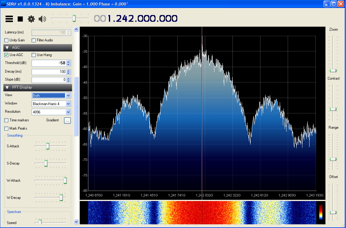
Modulator
rpidatv is located in rpidatv/bin folder
rpidatv -2.0.0
Usage:
rpidatv -i File Input -s Symbolrate -c Fec [-o OutputMode] [-f frequency output]  [-l] [-p Power] [-h]
-i            path to Transport File Input
-s            SymbolRate in KS (125-4000)
-c            Fec : 1/2 or 3/4 or 5/6 or 7/8
-m            OutputMode
	      {RF(Modulate QSK in RF need -f option to set frequency)}
              {IQ(Output QPSK I/Q}
              {PARALLEL(Output parallel (DTX1,MINIMOD..)}
       	      {IQWITHCLK(Output I/Q with CLK (F5LGJ)}
	      {DIGITHIN (Output I/Q for Digithin)}
-f 	      Frequency to output in RF Mode in MHZ
-l            loop file input
-p 	      Power on output 1..7
-x 	      GPIO Pin output for I or RF {12,18,40}
-y	      GPIO Pin output for Q {13,19,41,45}
-h            help (print this help).
Example : sudo ./rpidatv -i sample.ts -s 250 -c 1/2 -o RF -f 437.5 -l
Transport stream
rpidatv needs a DVB transport stream in input. In the past, ffmpeg was used to generate transport stream. Because ffmpeg is not completely DVB compliant and induces latency, an other tool is proposed : avc2ts
H264 encoder and transport stream encapsulator
avc2ts is located in rpidatv/bin folder
avc2ts -1.0.0
Usage:
rpi-avc2ts  -o OutputFile -b BitrateVideo -m BitrateMux -x VideoWidth  -y VideoHeight -f Framerate -n MulticastGroup [-d PTS/PCR][-v][-h]
-o            path to Transport File Output
-b            VideoBitrate in bit/s
-m            Multiplex Bitrate (should be around 1.4 VideoBitrate)
-x            VideoWidth (should be 16 pixel aligned)
-y 	      VideoHeight (should be 16 pixel aligned)
-f            Framerate (25 for example)
-n 	      Multicast group (optionnal) example 230.0.0.1:10000
-d 	      Delay PTS/PCR in ms
-v	      Enable Motion vectors
-i	      IDR Period
-t		TypeInput {0=Picamera,1=InternalPatern,2=USB Camera,3=Rpi Display,4=VNC}
-e 		Extra Arg:
			- For usb camera name of device (/dev/video0)
			- For VNC : IP address of VNC Server. Password must be datv
-p 		Set the PidStart: Set PMT=PIDStart,Pidvideo=PidStart+1,PidAudio=PidStart+2
-s 		Set Servicename : Typically CALL
-h            help (print this help).
Example : ./rpi-avc2ts -o result.ts -b 1000000 -m 1400000 -x 640 -y 480 -f 25 -n 230.0.0.1:1000
Console interface
A console interface is provided under rpidatv/scripts
$ /home/pi/rpidatv/scripts/gbmenu.sh
Touchscreen interface
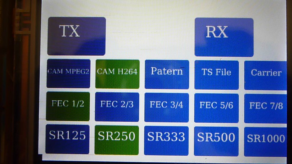 A graphical interface is provided under rpidatv/bin/ folder
$ /home/pi/rpidatv/bin/rpidatvgui